

Content last revised on September 10, 2026
Backlight Driving, Acoustic Noise, and EMI Considerations
When a display assembly is removed from an industrial console, record the original backlight wiring, connector orientation, and cable routing before substitution. A visible image with a dark screen can result from a backlight circuit, display timing path, power sequence, or panel fault, so the first test should compare the panel with a known operating signal path rather than assigning one cause from the symptom alone.
The supplied data for LQ121S1LG51 identifies the unit as a TFT LCD Display Module, but it does not confirm whether the specific assembly uses a cold cathode fluorescent lamp or an LED backlight. The requested comparison between high voltage cold ignition and constant current LED driving is therefore an integration topic, not an official parameter of this model. Designers should verify the original backlight architecture, driver requirements, connector pinout, enable logic, and dimming method from the panel documentation. Do not connect a replacement backlight driver until those details have been checked.
For a PWM controlled system, an engineer can observe the backlight supply and control waveform with suitable isolated measurement equipment. Listen for buzz only after confirming that the sound is not produced by a nearby inductor, transformer, mounting bracket, or enclosure panel. Acoustic noise can be coupled mechanically through the display frame, while electromagnetic interference can enter through the power harness, signal cable, or grounding arrangement. A frequency sweep across the system operating range may help identify a resonance, but any acceptance limit must come from the equipment specification.
The requested claims for a fixed optical contrast ratio above 500:1 at 50,000 lux, an anti glare coating, or a 50,000 hour half brightness life are not present in the supplied factory parameter set. They must not be presented as confirmed characteristics of LQ121S1LG51. If the panel is being considered for a surgical navigation monitor or ultrasound diagnostic display, the complete display assembly should be assessed for luminance, contrast, glare, uniformity, image retention, electrical safety, and applicable system level regulatory requirements. The LCD module alone does not establish medical equipment compliance or EMC certification.
As a Design Consideration, keep high current backlight wiring physically separate from sensitive video wiring where the enclosure permits. Terminate cable shields according to the equipment grounding architecture, avoid unnecessary cable loops, and verify emissions with the completed enclosure and operating drive electronics. A component cannot independently claim compliance with a complete system standard such as CISPR or EN 55011.
Image Quality and Temperature Evaluation
Before evaluating image quality, allow the display assembly and the surrounding enclosure to reach a stable condition. Inspect the front surface for pressure marks, uneven bezel loading, and local contact between the glass and the mounting frame. Mechanical stress can change the apparent uniformity of an LCD image, particularly when the panel is installed against an uneven cabinet surface. Fastener loading should be distributed evenly according to the equipment manufacturer’s mechanical instructions.
The factory information supplied for this product does not confirm whether the liquid crystal mode is TN, IPS, or MVA. It also does not specify viewing cone values such as 85 degrees in each direction, grayscale inversion behavior, gamma voltage settings, or temperature compensation data. These requested characteristics must remain unverified until the applicable Sharp datasheet is available. The same rule applies to an AG etched surface. A technician may inspect the installed surface under controlled lighting, but the observation should not be converted into an unverified coating specification.
In a repair evaluation, compare a neutral gray ramp, near black levels, saturated colors, and fine text at the operator’s normal viewing position. Repeat the check from practical side and vertical angles used by the equipment operator. Color shift or grayscale changes may be related to panel technology, timing configuration, temperature, optical stack condition, or source signal settings. Verify the panel against a known good assembly and review the controller configuration before replacing other system components.
The T-CON board and source controller should be treated as a matched timing environment. The supplied product record does not specify LVDS or TTL signaling, lane count, pixel clock, differential impedance, skew allowance, gamma reference, or power sequencing. If the original system uses a differential video interface, the integrator should confirm the documented cable arrangement and termination requirements. A commonly used differential impedance target may exist in the host design, but it is a Design Consideration for the complete link, not an LQ121S1LG51 factory specification.
Temperature tracking should be assessed at the system level when the panel is installed in a sealed HMI or a diagnostic display enclosure. Check whether heat from the processor, backlight driver, or nearby power electronics creates a local hot area behind the panel. At low temperature, inspect the equipment for condensation risk before energizing it. The display supplier’s documented operating and storage limits should be used for the final decision. If those limits are unavailable, the installation team should not create substitute limits from general LCD practice.
For a same size or same resolution replacement evaluation, engineers may also review LMS700KF01-001. Compatibility still requires confirmation of mechanical outline, active area, connector position, signal protocol, backlight control, optical performance, and electrical timing. A similar category or diagonal size does not by itself establish interchangeability.
FFC/FPC Grounding and Cable Routing Considerations
Inspect the flexible cable before removing the panel from its frame. Look for sharp bends, crease marks, lifted stiffeners, contamination on contacts, and evidence that the cable has been pulled sideways during service. Photograph the original routing and the connector lock position. Reinstalling a cable with altered routing can change its coupling to motor, inverter, relay, or switching power wiring, even when the connector appears fully seated.
The supplied data does not define the connector shell, FFC or FPC pin assignment, LVDS mapping, shield termination, or chassis bonding arrangement for LQ121S1LG51. Do not assume that an exposed metal shell is a signal ground or that every visible cable shield should be connected at both ends. The integrator should confirm the original drawing and then verify continuity, isolation where required, and the return path to the host controller.
Near a variable frequency drive or servo amplifier, pixel jitter, horizontal bands, or intermittent image loss may indicate a signal integrity, grounding, power quality, or timing problem. Use a known good cable and compare the display waveform at the controller and panel ends where test access is available. An oscilloscope can help identify ringing, common mode disturbance, unstable clock behavior, or loss of data margin. It cannot replace the panel manufacturer’s pinout and timing documentation.
Common mode ferrite components can be evaluated as part of the host system’s EMC design, but their impedance profile, placement, and effect on the signal must be tested with the actual cable and operating frequency. Adding an unverified component directly to a panel interface may introduce attenuation or reflections. The practical engineering objective is to control the coupling path while preserving the signal quality required by the display controller.
Backlight endurance is also a system issue. The available factory data does not provide an LED backlight half brightness curve, a 50,000 hour rating, an MTBF value, or a decay model for this exact part. Any lifetime statement must therefore be obtained from an authoritative Sharp specification or reliability document. During maintenance, inspect the rear clearance, airflow path, connector strain relief, and heat transfer route around the display assembly. Local heating can affect image uniformity and may shorten the life of associated electronics, but no model specific lifetime prediction should be made without source data.
Maintenance Note: Disconnect power before removing the display cable, and inspect the enclosure ventilation path and sealing gasket during every planned service interval.
For broader enclosure, grounding, thermal, and HMI integration considerations, consult the Industrial Display and HMI Solutions engineering resource. It provides system level context without replacing the original documentation for this Sharp panel.
Full-Screen Primary-Color Screening for Subpixels and Uniformity
After installation, begin optical screening with a full screen white image, followed by red, green, and blue test fields generated by the known good controller. Observe the image at normal operating brightness and record any fixed dark point, bright point, vertical line, horizontal line, color patch, flicker, or edge shading. Repeat the test after the display has warmed under the same conditions used by the equipment.
A three stage primary color check helps separate a pixel level defect from a backlight or optical uniformity issue. A defect that remains fixed with the image content may require inspection of the panel signal path, while broad illumination variation may require examination of the backlight assembly, diffuser condition, frame pressure, or power driver. These observations are diagnostic clues rather than proof of a particular internal failure.
A 45 degree flashlight inspection can be used with the display switched off to identify scratches, pressure marks, contamination, and localized shadowing. With the display operating, compare the same region under white and primary color fields. Avoid pressing the glass during this test. Surface pressure can temporarily alter the optical appearance and make a mechanical issue appear to be a pixel defect.
The supplied factory data does not confirm a contrast ratio above 500:1 at 50,000 lux, a particular anti glare treatment, pixel defect class, uniformity tolerance, or AOI acceptance limit. If the panel is evaluated for a high precision surgical or ultrasound diagnostic display, those limits must be established by the equipment manufacturer, applicable quality procedure, and relevant display documentation. A visual bench inspection cannot establish diagnostic image compliance.
Check the controller configuration when colors appear incorrect or grayscale transitions look compressed. Confirm that the video format, timing, cable orientation, backlight enable sequence, and panel identification match the original assembly. If the image is unstable, compare the source signal with a known good display before concluding that the LCD glass is defective. If the unit is being installed into a different HMI platform, the system designer should complete electrical, mechanical, optical, thermal, and EMC validation before release.
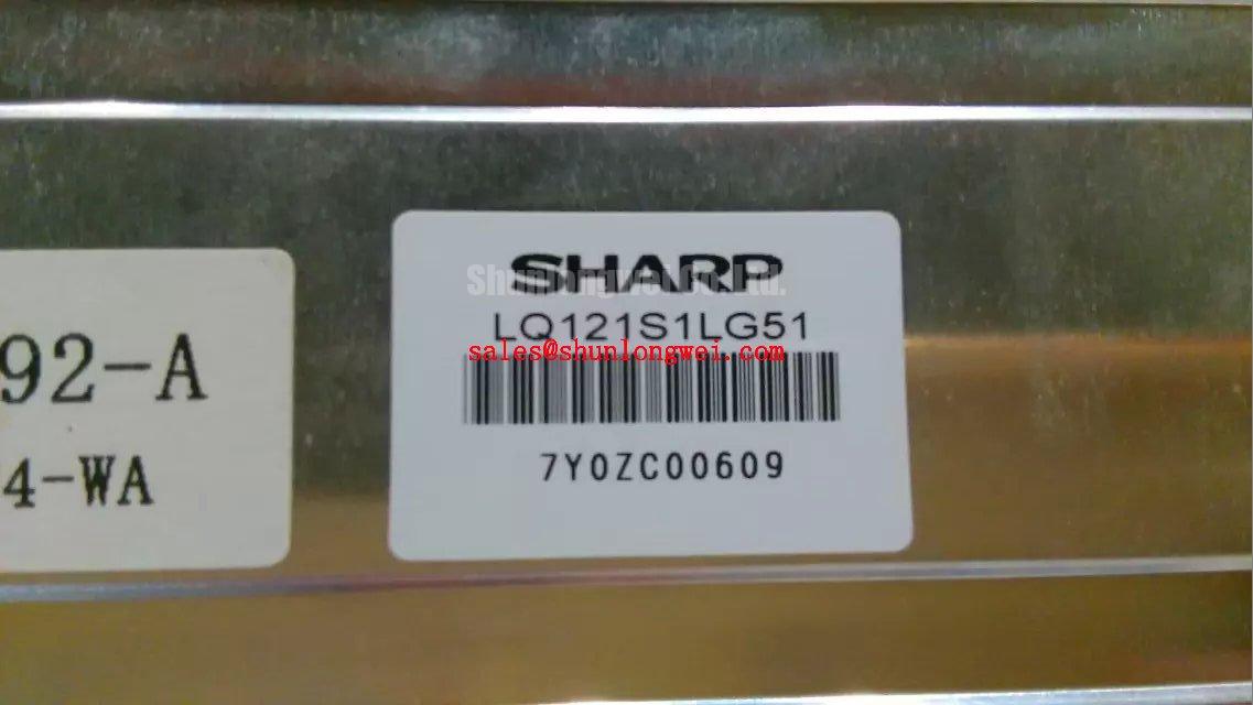
For procurement and repair records, retain the model marking, supplier documentation, inspection results, and equipment revision used during evaluation. The confirmed identity of this unit is Sharp LQ121S1LG51, categorized as an industrial grade LCD/HMI panel and supplied as a TFT LCD Display Module. Unconfirmed resolution, interface, backlight, optical, and environmental values should remain open verification items until supported by the original factory documentation.