Content last revised on September 10, 2026
LQ121S1LG41 Industrial LCD Module Inspection and Compatibility
Before fitting LQ121S1LG41, inspect the TFT glass perimeter, bezel seating surfaces, rear housing, and cable interface area under clean light, then compare the original equipment documentation against the replacement module before any power connection.
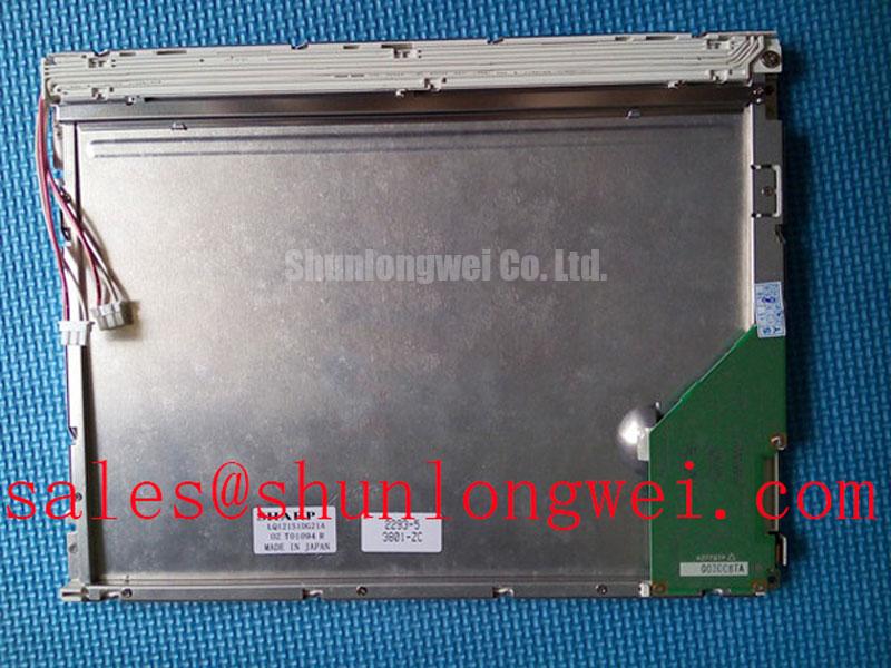
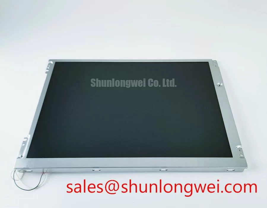
The Sharp LQ121S1LG41 is an industrial grade LCD/HMI panel supplied as a TFT LCD display module. Its documented product information identifies it as a display module for industrial HMI integration. Electrical input requirements, interface pin assignment, backlight arrangement, optical performance, mechanical dimensions, environmental ratings, and timing limits must be verified from the original panel documentation and the host equipment records before installation.
For repair work, compatibility should be assessed as a complete assembly question rather than a screen appearance question. The technician should confirm the panel marking, display active area, mounting geometry, connector location, signal format, power sequencing, backlight supply arrangement, and controller board configuration. A physically similar display can still be unsuitable if its interface mapping or electrical sequence differs from the original installed panel.
| Item | Verified Product Information |
|---|---|
| Model | LQ121S1LG41 |
| Manufacturer | Sharp |
| Product category | Industrial Grade LCD/HMI Panel |
| Module construction | TFT LCD Display Module |
| Specification status | Model information identified; application specifications require documentation verification |
Constant Luminance Output Control and Backlight Life Verification
A display that powers up with an apparently normal image can still require further inspection if brightness is uneven across the viewing area. During preventive maintenance, compare illumination from the center toward each edge while the host equipment is operating at its normal brightness setting. Edge shading, localized bright zones, unstable brightness after warm up, or intermittent illumination should be investigated through the complete backlight drive path rather than attributed to the LCD module alone.
The official product information available for LQ121S1LG41 confirms the TFT LCD module category but does not establish a backlight type, luminance value, LED lifetime rating, L70 value, B50 value, dimming method, or dimming frequency. These properties must therefore not be assumed for this model. The system integrator should verify the backlight supply and control requirements from the original panel documentation and the equipment controller schematic.
Design Consideration: stable backlight output depends on the interaction of the display module, backlight driver, harness, heat path, enclosure airflow, and operator brightness settings. In a sealed telematics enclosure, retained heat around a display edge can affect long term optical uniformity and driver stability. Maintenance teams should inspect whether chassis contact areas, thermal interfaces, and display support rails remain clean and evenly seated, especially after vibration service or enclosure repair.
Where pulse width modulation is used by the host controller, its frequency and duty cycle behavior should be checked against the display and backlight driver documentation. Poorly coordinated dimming control can present as visual flicker, brightness stepping, or audible noise from surrounding power circuitry. An oscilloscope comparison with a known good equipment channel can help separate a control signal issue from a driver or display assembly issue.
⚠️ Maintenance Note: Disconnect system power and allow stored energy in the display power circuit to discharge before reconnecting a display cable or backlight harness.
For AGV and forklift telematics service, ambient light should be considered during the equipment level assessment. Anti glare or anti reflective surface treatment must not be assumed unless confirmed by the original panel specification. If a front cover lens is installed over the display, inspect the lens, gasket compression, and contamination level because external surface damage can reduce readability even when the TFT module itself remains electrically functional.
LVDS Timing, Pixel Clock, and Skew Compensation Verification
Before connecting LQ121S1LG41 to a replacement controller board or existing harness, document the original connector orientation and inspect the cable for creasing, conductor exposure, latch damage, and strain at the cabinet entry point. A display showing split images, repeated image sections, color displacement, intermittent horizontal bands, or a blank but powered screen can involve interface assignment, cable integrity, display timing, power sequencing, or controller output. These observations do not establish one single cause.
The available official factory information does not confirm whether this model uses a 20 pin or 30 pin interface, LVDS signaling, a specific pixel clock, a 3.3 V or 5.0 V logic rail, or JEIDA or VESA data mapping. Such values must not be inferred from the model category or from visual similarity to another industrial panel. The system integrator should verify the required supply voltage, connector pinout, signal format, and power on sequence from the original panel documentation.
Design Consideration: differential display links depend on controlled pair routing, continuity of the signal return path, and matched behavior between paired conductors. In equipment with long internal cable runs, vibration can weaken connector retention or disturb cable shielding. Inspect the mating connector and cable restraint before changing firmware settings or replacing controller boards. If signal quality is in doubt, verify the waveform at the source and at the panel end against a known good signal path.
Power sequencing requires the display, the interface board, and the backlight circuit to be treated as one coordinated system. Applying a supply or logic signal outside the sequence required by the original module documentation can create unstable startup behavior or prevent image initialization. Engineering Recommendation: capture the original startup sequence when a known good machine is available, then use that observation together with the relevant official documentation during repair validation.
When a replacement assessment is required, the LMS700KF01-001 can be reviewed as a separate verified display model. It should not be treated as an automatic substitute for LQ121S1LG41. Mechanical fit, interface format, electrical requirements, optical characteristics, and host controller compatibility all require independent confirmation.
High Humidity Storage Margins and Delamination Prevention Protocols
Store the display module in a clean, dry, electrically protected location and avoid placing heavy objects across the bezel or rear housing. Before installation after storage or transport, allow the module and the host enclosure to reach a stable temperature condition. This reduces the risk that condensation on external surfaces is mistaken for a display defect during initial power up.
No official storage humidity limit, operating temperature range, thermal cycling range, response time, liquid crystal behavior, or perimeter seal construction value has been provided for LQ121S1LG41. Statements about operation at specific humidity levels, subzero performance, high temperature endurance, or sealant composition would therefore be unsupported. Maintenance planning should use the environmental requirements stated in the original Sharp documentation and the specifications of the complete HMI enclosure.
Design Consideration: moisture management in an industrial display assembly involves the panel, front gasket, enclosure seams, cable glands, vents, and temperature transitions. An enclosure can be resistant to dust yet still develop condensation if warm humid air is trapped and then cooled. During inspection, look for signs of damaged perimeter sealing, loose mounting hardware, contamination around the front cover interface, and moisture paths near cable entries.
Mechanical mounting should distribute pressure evenly around the display support points. Over tightened fasteners, distorted brackets, or an uneven front bezel can place stress on the panel stack and can contribute to localized light nonuniformity. The mounting method, torque requirement, washer arrangement, and support locations should be determined by the equipment manufacturer’s mechanical drawing rather than by a generic panel mounting rule.
For rugged AGV and forklift telematics displays, vibration exposure and repeated temperature transitions make enclosure maintenance especially important. The display itself should be evaluated together with the mounting frame, protective window, cable clamp, and gasket condition. Useful reliability practices for industrial display assemblies are discussed in the Industrial Display & HMI Solutions engineering guide.
Industrial EMI Noise Immunity, Chassis Shielding Continuity, and Common Mode Suppression
When horizontal noise bands, intermittent pixel shimmer, or image instability appear near motor operation, begin with an observation log. Record whether the symptom changes with drive speed, charger connection, hydraulic pump operation, chassis bonding condition, cable position, or cabinet door position. This approach helps distinguish a display symptom from an interference condition in the surrounding electrical system.
The official information for LQ121S1LG41 does not provide an EMC immunity classification, cable shield requirement, ferrite specification, differential impedance requirement, skew budget, or independent certification claim. The display module must not be represented as independently compliant with complete system EMC standards. EMC performance is established at equipment level through the interaction of the display, controller, cable assembly, chassis, power conversion circuits, enclosure, and installation environment.
Design Consideration: maintain a continuous and low resistance chassis bonding path where the equipment design calls for shield termination. A shield that is left floating, interrupted by paint, or routed through an unsuitable connector transition can reduce the effectiveness of the original cable strategy. Technicians should preserve the original cable routing and clamp arrangement during panel replacement, then verify operation with nearby power electronics active.
Common mode suppression components can be considered only after the original cable and grounding arrangement has been inspected. Their selection depends on the actual signaling method, frequency behavior, cable construction, and measured interference path. System engineers should validate any suppression change through equipment level testing so that image integrity is preserved without creating signal attenuation or startup problems.
For a forklift or AGV telematics enclosure operating near inverter driven motors, inspect power and signal harness separation, connector shell contact, chassis bonding hardware, and the physical condition of cable shielding. A stable display image after these checks supports a more reliable repair decision than replacing the TFT module based on visual symptoms alone.