Content last revised on September 10, 2026
Radiated Emissions and Backplate Multi-Point Star Grounding
When the Sharp LQ121S1DG21A is evaluated near variable-frequency motor drives, switching supplies, or long harnesses, inspect the complete display installation as an electromagnetic system. Pixel jitter, horizontal noise bands, intermittent image loss, and unstable touch or control-panel behavior may be associated with common-mode coupling, shield termination, reference-plane discontinuity, or an upstream signal-integrity problem. These symptoms should be checked against a known-good signal path with an oscilloscope or service diagnostic interface rather than assigned to the LCD module without measurement.
A backplate grounding arrangement can be considered where the equipment chassis provides a suitable protective and functional reference. The design objective is to create a low-impedance return path for unwanted common-mode current while avoiding ground loops between the display frame, controller enclosure, cable shield, and power-supply return. Engineers should determine the grounding topology from the equipment safety architecture and EMC test plan. A display module by itself cannot be claimed to meet CISPR Class A or Class B limits because those limits apply to the completed equipment and its operating configuration.
For an LVDS or FFC-connected assembly, inspect the full cable route, shield continuity, connector retention, and proximity to high-current switching conductors. A cable that is properly seated at the panel but routed alongside an inverter output can still produce unstable data reception. Common-mode ferrite components may be evaluated as a system-level Design Consideration when conducted or radiated interference has been confirmed, but their impedance profile, placement, current rating, and effect on the differential waveform must be validated on the actual assembly.
During fault isolation, compare the display-side waveform with the controller-side waveform while checking the backlight and logic rails independently. If the image changes when the harness is moved, inspect connector locking force, contact alignment, strain relief, and cable bend stress. Do not use a brightness or contrast adjustment to mask a data-integrity fault. The LMS700KF01-001 may also be reviewed as a separate same-class display replacement candidate, but its electrical, mechanical, and optical compatibility must be verified independently rather than inferred from size or appearance.
Backlight lifetime figures, including any claimed brightness-retention period or MTBF curve, are not included in the supplied factory parameter set for this page. A maintenance specification should therefore record measured luminance, driver current behavior, thermal conditions, and operating hours from the complete equipment if long-term service planning is required. Such records are field data for the assembled system, not an automatic rating of the LQ121S1DG21A itself.
Flush-Mount Open-Frame Bezel Integration & Perimeter Gasket Shock Isolation
Before removing the failed panel, record the bezel opening, mounting-hole pattern, connector clearance, cable exit direction, and the position of any compression gasket. The supplied factory data identifies the product as a TFT-LCD Display Module but does not provide an outer bezel drawing or mounting tolerance. Use the original Sharp mechanical drawing or the equipment manufacturer’s service drawing to confirm the envelope. A panel that fits the opening can still impose unacceptable stress if the frame, gasket, or mounting points are misaligned.
Flush-mount integration should allow the display frame to sit evenly against the intended support surface without twisting. The chassis should carry the mounting load, while the display viewing area remains free from concentrated pressure. Uneven fastening, a gasket that is too thick, or a distorted opening may create visible non-uniformity, local darkening, pressure marks, or image changes when the enclosure is tightened. These observations are not sufficient to identify an internal panel defect; release the mounting load and repeat the visual check before making a replacement decision.
Cross-pattern tightening is a general Design Consideration for distributed mechanical loading, not an official LQ121S1DG21A specification. The final fastener type, torque, washer arrangement, gasket compression, and chassis material should be determined by the equipment designer or original service documentation. Vibration and shock testing should be performed on the complete mounted assembly, with attention to cable strain, connector latch retention, and any movement between the panel frame and enclosure.
⚠️ Field Alert: Disconnect equipment power and allow stored energy to discharge before inserting or removing the display cable, because live connector handling can expose signal contacts to unintended electrical stress.
For an open-frame industrial HMI, flexible cable routing deserves the same attention as the bezel. Keep the bend path smooth, avoid folding directly at the connector body, and provide strain relief so enclosure movement is not transferred into the contact area. If the existing FFC shows whitening, crease lines, exposed conductor edges, or inconsistent contact pressure, replace the cable or connector hardware according to the equipment service procedure before condemning the panel.
Railway cab displays and passenger information terminals can experience repeated vibration, door or cabinet shock, thermal expansion, and maintenance handling. The LQ121S1DG21A should be assessed within the installed enclosure, including gasket behavior, frame support, cable retention, and thermal clearance. The product category alone does not establish a railway approval, vibration rating, ingress rating, or safety certification. Those requirements remain system-level compliance items.
Full-Screen Primary Color AOI Screening: Stuck Sub-Pixels & Background Uniformity Audit
After installation on a controlled test bench, display a full-screen sequence of primary colors, neutral gray, black, and white using the approved controller configuration. Inspect the active area from the normal service viewing position and then from an oblique angle. Look for stuck sub-pixels, vertical or horizontal line defects, uneven background fields, intermittent regions, and changes that appear when the cable or enclosure is gently stabilized. Automated optical inspection can improve repeatability, but the acceptance criteria must come from the equipment owner or panel documentation.
A 45-degree flashlight inspection can help separate an unlit image from a completely absent image. With the display unpowered, use controlled oblique illumination to inspect the surface for scratches, contamination, pressure marks, or handling damage. With the system powered, compare the visible image, backlight state, and controller output. A dark screen with visible image content under suitable illumination suggests a different diagnostic path from a screen with no valid data, but the observation does not identify one exclusive failure cause.
Backlight and image data should be checked separately. Verify the backlight driver input, enable behavior, current regulation, and thermal condition using the equipment schematic. Do not assume that the panel uses a particular backlight voltage, current, or dimming method unless the original documentation confirms it. PWM frequency and duty-cycle behavior are system-dependent; if visible flicker, audible noise, or brightness instability is reported, measure the driver waveform and compare it with the approved driver specification.
For industrial HMI interfaces that display fixed menus, status bars, or route information for long periods, rotate test content during service evaluation and inspect for residual image behavior after the content changes. Any long-term image-retention assessment should use the operating temperature, brightness setting, duty cycle, and content pattern of the actual equipment. A general LCD technology article such as The Ultimate Guide to Industrial TFT-LCD Technology can provide background for technology selection, while the exact acceptance limits must remain tied to the panel and system documentation.
When an apparent line defect remains fixed in the same screen position across multiple input images, document its location, temperature condition, cable state, and repeatability. When the defect moves or changes with the controller output, inspect the source timing, mapping, cable contacts, and connector seating. This evidence-based separation prevents a backlight problem from being confused with a data-path problem and avoids replacing a serviceable module without confirmation.
Logic Supply Voltage Sequencing to Reduce Driver IC Latch-Up Risk
Do not apply an assumed logic voltage to the Sharp LQ121S1DG21A. The supplied factory parameter set does not state whether the installed equipment requires a particular logic supply, power-on rise time, interface mapping, or backlight control arrangement. The system integrator should verify the required supply voltage from the original panel documentation and then confirm it at the panel connector with an appropriately rated instrument.
Power sequencing should be reviewed when the field symptom includes a white screen, delayed image, intermittent start-up, residual image after shutdown, or a display that recovers only after a complete power removal. Measure the controller output, panel logic rail, reset or enable signals, and backlight control in their actual time relationship. The purpose is to ensure that data and control pins do not become active outside the permitted operating conditions of the panel interface. The correct timing limits are system-determined unless they are stated in the exact factory documentation.
Check the differential interface routing for controlled impedance, pair continuity, polarity, termination, and mapping. A nominal 100-ohm differential routing target may be specified by a particular interface design, but it must not be treated as an LQ121S1DG21A factory value without documentation. Likewise, JEIDA or VESA mapping should be selected only after confirming the panel revision and controller configuration. Incorrect mapping can present as incorrect colors, split-screen artifacts, unstable synchronization, or a partially populated image.
At the connector, inspect for pushed-back contacts, contamination, incomplete latch engagement, and excessive cable movement. Compare resistance and continuity only with the equipment isolated and the connector pinout confirmed. If the display starts correctly after repeated power cycles, capture the supply waveform during both successful and unsuccessful starts. This helps distinguish a sequencing issue from a marginal connector, controller reset condition, unstable supply, or backlight enable fault.
Direct sunlight and high ambient illumination can reduce perceived contrast even when the panel is functioning correctly. The supplied data does not specify a contrast ratio, sunlight readability value, anti-glare coating, or optical operating limit for this exact unit. Designers should evaluate the installed cover glass, viewing angle, enclosure shading, brightness control, and thermal rise under the actual cab or passenger-information installation conditions. Any optical acceptance test should use the equipment’s required viewing geometry and documented environmental limits.
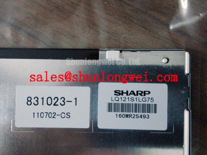
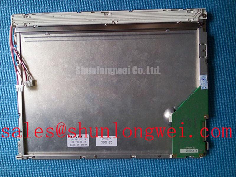
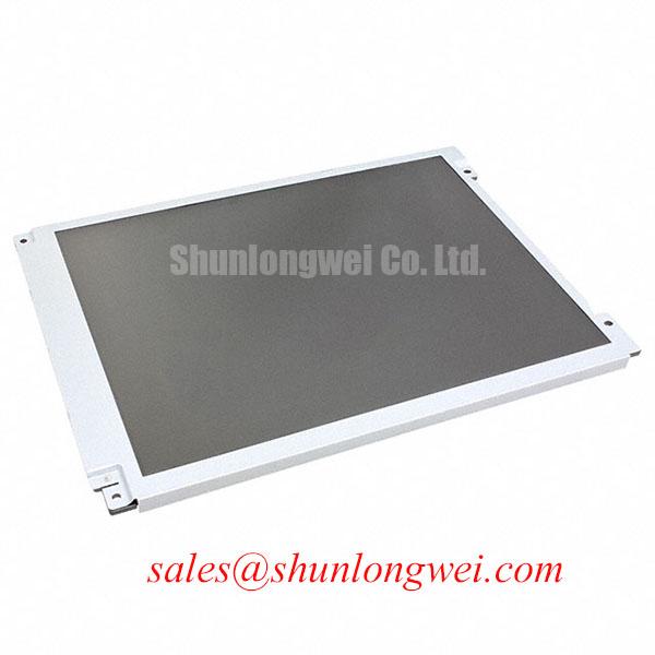
For procurement and emergency repair, record the complete marking, module revision, connector arrangement, host controller type, and mechanical interface before placing the LQ121S1DG21A into service. Sharp is the identified manufacturer, and the product is categorized as an Industrial Grade LCD/HMI Panel in TFT-LCD Display Module form. Compatibility remains dependent on the original system documentation and verification testing.