

Content last revised on September 10, 2026
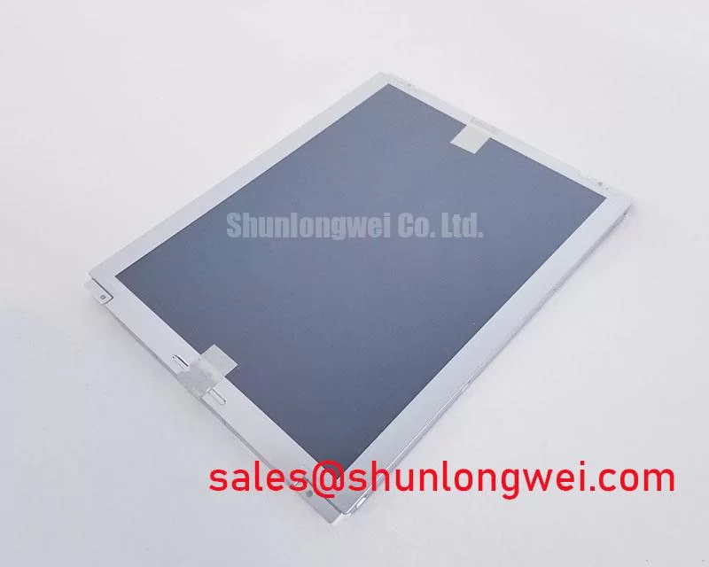
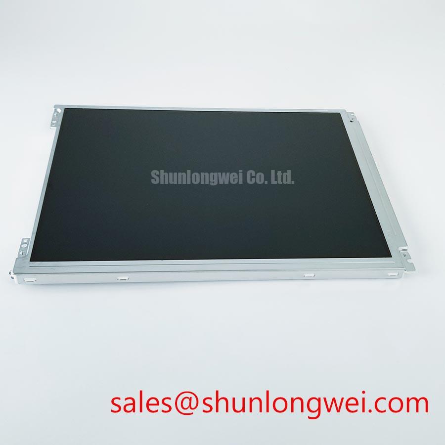
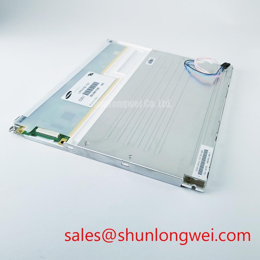
LTM121SI-T01 Toshiba / Samsung Industrial Grade TFT LCD Display Module
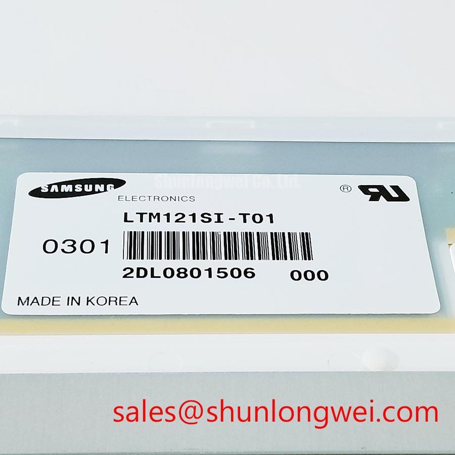
Begin replacement work by isolating power, inspecting the display frame and connector area, and comparing the removed unit’s identification label with LTM121SI-T01 before applying power. This product is listed as an Industrial Grade LCD/HMI Panel manufactured by Toshiba / Samsung and supplied as a TFT LCD display module. The available factory specification identifies the product category, manufacturer, module form, and official specification status, but it does not establish unlisted values such as resolution, brightness, interface pinout, backlight type, viewing angle, or operating temperature.
| Model | LTM121SI-T01 |
| Manufacturer | Toshiba / Samsung |
| Product Category | Industrial Grade LCD/HMI Panel |
| Module Type | TFT-LCD Display Module |
| Specification Status | Official Factory Spec Verified |
For a repair engineer, the practical value of this identification is compatibility control. The original equipment documentation should be checked for mechanical cutout dimensions, connector orientation, signal assignment, supply requirements, backlight drive arrangement, and mounting details. The system integrator should verify the required supply voltage from the original panel documentation rather than assuming a common LCD supply standard.
Controlled 100 Ohm Differential Impedance Flex Routing to Suppress High Frequency Jitter
When the host equipment uses an LVDS or comparable differential display connection, inspect the complete signal path before installing the replacement module. Check the cable locking mechanism, exposed contacts, ground return, bend radius, and routing beside switching power stages. A differential pair should be routed as a controlled impedance structure only when the host interface documentation defines that requirement. As a Design Consideration, a 100 Ω differential target with a tolerance defined by the system interface may be used for evaluation, but this is not an official electrical specification for LTM121SI-T01.
Power sequencing also belongs to the host system verification plan. Engineers should confirm the actual logic supply, enable timing, reset behavior, and data mapping from the original panel documentation. The frequently used 3.3 V or 5.0 V assumptions must not be applied to this model without evidence. If the panel image appears split, unstable, or incorrectly mapped, compare the data mapping and clock relationship with a known good assembly before changing hardware. A scope check at the panel connector can help distinguish a supply rise-time issue from a signal integrity problem.
Ambient light evaluation should be performed with the final bezel, cover glass, and viewing direction installed. Contrast performance under direct sunlight, including any target above 500:1 at high illumination, is a Design Consideration for the completed display system and must not be presented as a factory rating for this model. Anti-glare performance likewise depends on the actual panel surface and surrounding optical stack.
Micro Twist Mechanical Stress Fracture Prevention on Glass Substrate Driver Bumps
Remove the failed display without twisting the glass or using the front surface as a lifting point. Uneven frame pressure can create intermittent lines, image regions that disappear when the bezel is touched, or permanent display defects. These symptoms require inspection rather than a single assumed diagnosis. Compare the panel while displaying primary red, green, and blue fields, then use a low-angle flashlight to observe dark shadows around the active area and edge connections. This three-color bench check can help separate a backlight or image-generation problem from a localized panel connection fault.
Mounting hardware should release mechanical stress evenly around the perimeter. The gasket must sit flat without folds, contamination, or compression concentrated at one corner. Industrial HMI enclosures should also be checked for frame distortion after reassembly. ⚠️ Maintenance Note: Check the cooling path and sealing gasket during scheduled service because blocked airflow or a deteriorated seal can increase thermal and contamination stress on the display assembly.
For high-interference equipment, differential routing and skew should be verified against the host interface design. A 100 Ω ± 10% differential impedance and skew below 50 ps may be used as an engineering evaluation target where the interface specification calls for it, not as a confirmed LTM121SI-T01 factory parameter. Board contamination and coating condition can also affect leakage and service reliability; engineers may consult this reference on Printed Circuit Board Solder Mask and Conformal Coating when reviewing the surrounding controller board.
Suppressing Pixel Jitter and Horizontal White Lines Near 400 V Motor Drives
When the display is installed near a variable-frequency motor drive, first separate the display cable from motor conductors and switching nodes, then verify the enclosure bonding and cable shield termination specified by the machine design. A shielded FFC or LVDS assembly may require controlled grounding at the intended reference points; adding an arbitrary connection at both ends can create an unwanted current path. The correct method is determined by the equipment topology and should be verified during switching tests.
Pixel jitter and horizontal white bands can involve cable coupling, reference movement, data timing, power disturbance, or a fault elsewhere in the display chain. Compare the panel supply and differential waveform with a known-good signal path while the motor drive changes state. A common-mode ferrite can be evaluated only after its impedance behavior, current rating, and effect on signal integrity have been reviewed. Circuit simulation may support this assessment, and the general SPICE methodology can be useful for examining the surrounding power and filter network.
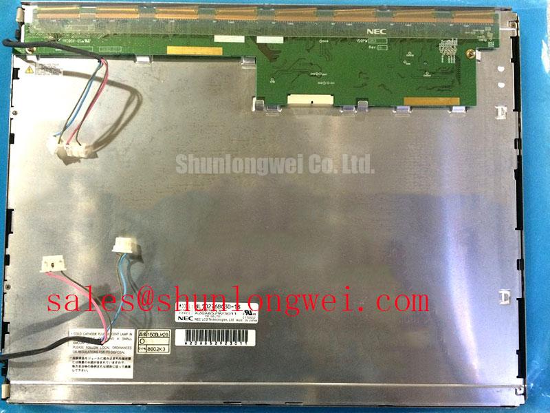
For replacement planning, the same-size or same-resolution compatibility review may include NL10276BC30-18. This is a separate device reference, not a claim of drop-in interchangeability. Mechanical, optical, electrical, and firmware compatibility must be confirmed by the equipment engineer.
Mitigating Gray to Gray Response Escalation During Cold Start
Cold-start evaluation should record the actual enclosure temperature, startup sequence, image content, and time required for the display to reach stable operation. Liquid-crystal response can change with temperature, but the available factory information for LTM121SI-T01 does not provide a verified GTG response specification or a confirmed operating range. Engineers should therefore use the original documentation and application test results when assessing cold operation rather than applying an assumed range such as −30 °C to +85 °C.
Condensation control is equally important. Allow the assembly and enclosure to reach a controlled temperature before exposing a cold module to humid air, and inspect the perimeter gasket and cable entry points for moisture paths. Mechanical seals, optical surfaces, and controller boards should be checked after thermal cycling because moisture or uneven expansion may produce symptoms that resemble a display timing fault.
Where the original system uses a coordinated display power or backlight subsystem, the auxiliary hardware should be reviewed separately. The NL128102BC28-04 reference may be evaluated as part of a related display power topology, subject to complete circuit compatibility checks. For broader panel interface, installation, and troubleshooting context, engineers can consult The Ultimate Guide to Industrial TFT LCD Technology.