Content last revised on October 18, 2026
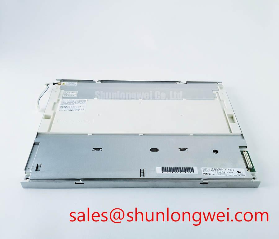
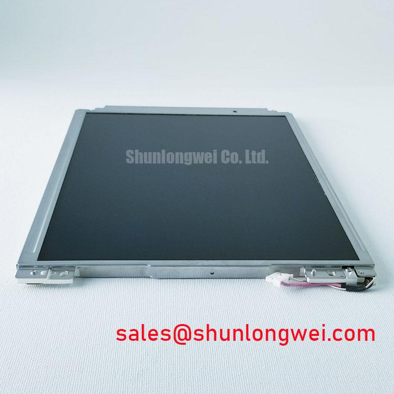
NEC NL8060BC31-47C 12.1 Inch SVGA LVDS TFT LCD Display
The NEC NL8060BC31-47C is a 12.1 inch industrial TFT LCD panel for equipment where a compact SVGA interface, wide viewing direction, and CCFL backlight arrangement must match the original display assembly. Its listed interface is LVDS, 1 channel, 6 bit, 20 pins, so replacement work should begin with the host controller pinout and cable orientation rather than assuming compatibility from screen size alone.
| Manufacturer | NEC |
| Model | NL8060BC31-47C |
| Screen size | 12.1 inches, 31 cm |
| Resolution | 800 RGB × 600, SVGA |
| Display technology | a-Si TFT-LCD, SFT |
| Brightness | 400 cd/m² typical |
| Contrast ratio | 600:1 typical |
| Viewing angle | 80°/80°/80°/80° typical, CR ≥ 10 |
| Interface | LVDS, 1 channel, 6 bit, 20 pins |
| Operating temperature | −10 to 70 °C |
| Backlight | Two CCFL lamps, no driver |
Polarizer Durability and Optical Retardation Film Inspection under Direct Industrial Lighting
Direct plant lighting can make surface reflections, gray-scale inversion, and uneven polarizer appearance more visible than they are on a service bench. For this panel, the official viewing-angle specification is 80°/80°/80°/80° typical at CR ≥ 10. That figure should be assessed as a viewing performance specification for this model, not treated as equivalent to the fully symmetric optical behavior of every IPS or MVA panel.
During incoming inspection, display a neutral gray field, white field, and dark field while observing the screen from the intended operator position and from the upper, lower, left, and right directions. Look for localized contrast change, edge haze, pressure marks, or areas that respond differently when the viewing angle changes. An anti-glare surface can reduce reflected factory lighting, but the actual result depends on the enclosure window, ambient illumination, and viewing geometry. Do not add an optical film or cover layer before checking whether it changes contrast or introduces a visible moiré pattern.
The LVDS transmitter should be evaluated as a complete signal path. Check the 20 pin cable orientation, pair continuity, connector seating, and the controller’s supported pixel format. When a service controller can output both TTL and LVDS, select the documented LVDS mode and compare the clock and data timing with a known-good panel assembly. Temperature testing should cover the specified −10 to 70 °C operating range, with attention to image stability during startup and after the panel reaches thermal equilibrium.
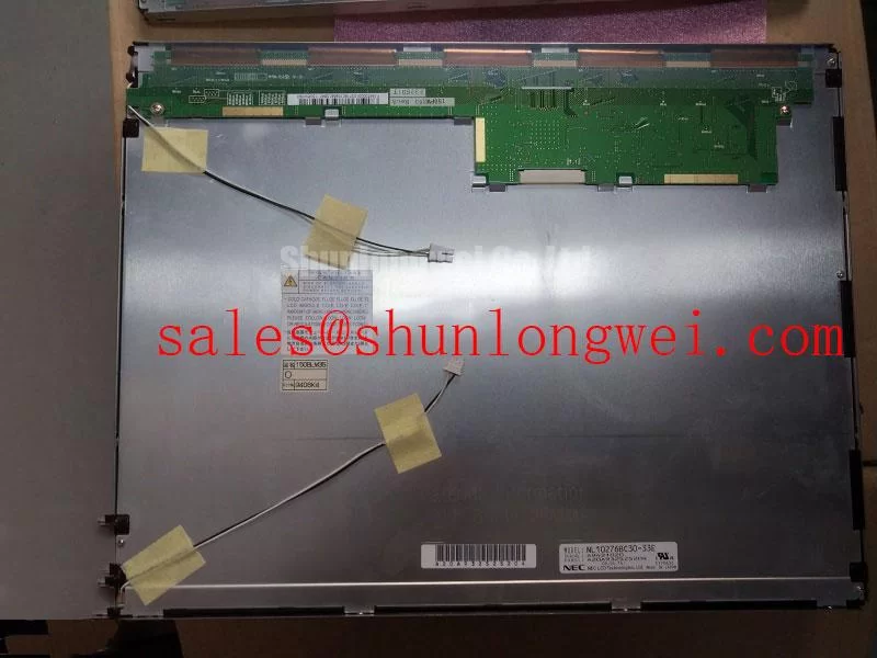
For a same-size service evaluation, engineers may also review NL6448AC18-08D. It should be treated as a separate compatibility candidate because connector assignment, timing, backlight requirements, and mechanical dimensions must be compared before any substitution.
Suppressing Acoustic Capacitor Buzz and EMI Emissions across 200 Hz to 1 kHz PWM Frequencies
The NL8060BC31-47C uses two CCFL backlights and is specified as no driver, which places the inverter and its switching behavior outside the panel’s listed backlight specification. A replacement assessment should therefore separate panel faults from inverter noise, lamp ignition behavior, and mechanical vibration in the surrounding assembly. Audible buzz that varies with brightness control should be correlated with the inverter drive waveform and enclosure resonance rather than assigned to the LCD glass without measurement.
Keep the high-voltage CCFL wiring physically separated from the LVDS cable and from sensitive controller circuitry. The inverter return path should be arranged according to the equipment manufacturer’s safety and insulation design. For a PWM-controlled system, record the brightness command, lamp current behavior, acoustic output, and screen uniformity at the actual operating frequencies used by the equipment. The panel itself does not provide a documented PWM range or a constant-current LED interface, so an LED driver should not be connected as a direct assumption.
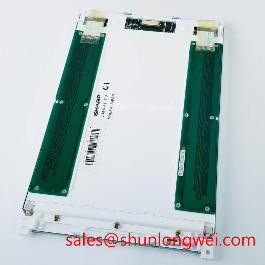
On the digital side, differential routing should preserve pair symmetry, controlled impedance, and a short return path. These are Design Considerations for reducing common-mode conversion and radiated emissions; the final layout depends on the host controller, cable construction, enclosure, and regulatory test setup. The linked LQ104S1DG61 can be reviewed as another display solution within a related system evaluation, but its electrical and optical specifications must not be transferred to this NEC panel.
Suppressing Pixel Jitter and Horizontal White Lines Induced by Adjacent 400V Motor Drives
When the display is installed near variable-frequency motor equipment, pixel jitter or horizontal bands should be investigated through cable routing and grounding before replacing the panel. Route the LVDS cable away from motor output conductors, switching nodes, and inverter input wiring. A shielded cable can help when its termination is compatible with the equipment’s grounding architecture, but the shield connection should be evaluated for unwanted circulating current.
At the panel connector, inspect for a partially inserted plug, uneven latch engagement, contact contamination, or a cable entering at an excessive bend angle. Re-seat the cable with power removed and compare the image while the motor drive is idle and operating. An oscilloscope comparison at the controller output and panel input can show whether the disturbance is already present at the source or is introduced along the cable path. Common-mode ferrites are Design Considerations rather than guaranteed accessories for this model; their effect should be validated against image timing and conducted noise.
The specified operating range begins at −10 °C. If the equipment is exposed to lower ambient conditions, image response and startup behavior fall outside the listed panel range and require system-level environmental evaluation. A heater, enclosure modification, or cable change should be selected by the system designer after observing the complete panel and controller response, not added as a presumed standard feature.
💡 Bench Tip: Protect the panel from ESD and insert the LVDS cable squarely, keeping the connector flat and fully latched before reconnecting power.
Thermal Cycling Degradation of Polarizer Adhesives and Sealant Gasket Integrity
Thermal cycling inspection should focus on visible optical change, connector reliability, and enclosure sealing while remaining within the documented −10 to 70 °C operating temperature range. A cold start can reveal slower liquid-crystal response, temporary contrast variation, or backlight ignition behavior that is not visible at room temperature. Record the time to a stable image, gray-field uniformity, and any residual image after a static test pattern is removed.
Do not infer adhesive, sealant, or internal film construction from the panel’s external appearance. Instead, inspect the perimeter for lifting, haze, contamination ingress, or pressure-related discoloration after the equipment has completed its approved environmental cycle. Mechanical compression from an incorrectly sized bezel can create localized optical defects even when the electrical interface is correct. The mounting frame should support the panel evenly without forcing the glass or bending the connector area.
For CNC operator panels and robot teach pendants, check whether the viewing window, gasket, and front bezel preserve the intended optical result under direct lighting. The Industrial Display & HMI Solutions guide provides broader enclosure and HMI integration context. For display technology background, engineers can also consult Tianma Industrial Display Solutions as an industry reference.
Power sequencing should be checked with the original panel and controller documentation. Confirm that logic power, LVDS activity, and CCFL inverter enable signals follow the specified order so that white-screen startup, flicker, or a persistent image is not confused with a panel replacement fault. Static HMI screens should also be rotated or managed according to the equipment operator’s display policy when long-term image retention is a concern.