




Content last revised on September 24, 2026
Suppressing Acoustic Capacitor Buzz & EMI Emissions across 200 Hz to 1 kHz PWM Frequencies
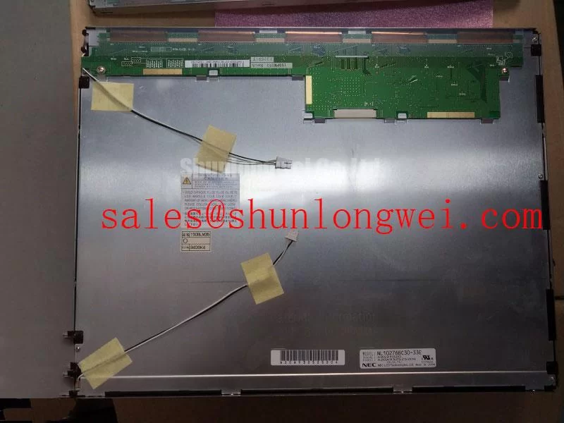
When a cabinet display produces audible noise during brightness changes, begin at the display power path rather than assuming that the panel itself is the source. Capacitors, inductors, driver assemblies, loose shielding parts, and an enclosure bezel can all transmit vibration. The NL10276BC30-33E should therefore be evaluated in the complete original display assembly, including its controller and illumination supply, because the verified module classification alone does not establish whether the host system uses a CCFL inverter or an LED driver.
The requested comparison between high voltage CCFL ignition in the 1500 to 1650 Vrms range and constant current LED dimming with 1000:1 PWM is a system level evaluation topic, not an official specification stated here for this NEC model. The system integrator should verify the required illumination technology, electrical limits, dimming method, and permissible PWM operating range from the original panel and controller documentation. Connecting an unsuitable backlight supply can damage the illumination circuit or create an unsafe service condition.
Acoustic noise that varies with display brightness may indicate a driver operating point, an inadequately restrained magnetic component, or coupling between the display assembly and the equipment enclosure. A useful diagnostic method is to observe whether the sound changes when the screen content changes, when brightness is adjusted, and when the enclosure cover is temporarily supported without altering electrical connections. This separates a mechanical resonance question from a display signal issue without assigning a single cause.
EMI control is also an integration matter. Cable routing, grounding continuity, shielding termination, controller layout, and power supply behavior influence emissions and susceptibility. The panel cannot be represented as independently compliant with an equipment level EMC standard. As a Design Consideration, maintain the original cable routing and shielding strategy, then validate the repaired system under its normal operating modes.
Direct sunlight readability depends on the complete optical stack, including the panel surface, protective window, enclosure geometry, and any front treatment fitted by the equipment manufacturer. Values such as a contrast ratio above 500:1 at 50,000 lux, anti glare coating performance, or illumination half life beyond 50,000 hours must not be attributed to this module without the applicable NEC documentation. If an outdoor or high ambient light installation is being assessed, measure the installed display at the actual operator viewing position and compare the result with the equipment requirement.
⚠️ Maintenance Note: Isolate equipment power before disconnecting the display cable, then inspect connector retention and the condition of enclosure gaskets before restoring service.
Digital RGB Bus Synchronization & Logic Power Rail Verification
A blank screen, unstable image, split image, incorrect colours, or intermittent recovery after power cycling requires a structured interface check. Confirm the connector is fully latched, inspect the flexible cable for sharp bends or compression marks, and compare each harness conductor location with the original panel documentation. The NL10276BC30-33E is identified as a TFT LCD display module, but the supplied verified product data does not state its specific digital interface, logic supply voltage, pinout, or timing sequence. The system integrator should verify the required supply voltage from the original panel documentation.
TTL 24 bit RGB synchronization, 3.3 V or 5.0 V logic rail selection, 0.5 ms < t1 < 10 ms rise time windows, 100 ohm differential routing, and JEIDA or VESA mapping are interface topics that must be validated only where the original design confirms their relevance. They are not presented as specifications for this NEC module. In particular, an interface that looks physically similar can still use a different signal convention or power sequence.
During a controlled repair evaluation, compare the suspect signal path against a known functioning path where available. Use suitable test equipment to examine supply stability, reset behavior, clock and synchronization activity, and cable integrity while avoiding probe loading or accidental shorts at fine pitch connectors. If the image fault changes when the cable is gently supported near a bend point, the result may indicate a connection or mechanical strain concern; it does not alone identify the panel as the failed item.
Power sequencing deserves attention where the host controller enables video before the display supply is stable, or removes one rail while another remains active. The engineering principle is to preserve the original sequence, prevent unintended signal injection during incomplete power states, and verify the observed timing against the equipment documentation. This approach can help distinguish a host controller startup issue from a display assembly issue.
FPC and flexible display cables should not be repeatedly folded along the same crease during bench testing. Route them with a relaxed bend and provide strain relief at the enclosure transition. This is a Design Consideration for service handling, not an NEC factory bend life rating. Where a same family panel is being reviewed for documented repair compatibility, the NL10276BC16-06 can be compared objectively against the original assembly for interface, optics, mechanics, and host firmware requirements.
LCD Grayscale Inversion Mitigation & Optimal Viewing Direction Alignment
Before diagnosing a brightness or colour complaint, inspect the display with a stable known image from the normal operator position and then from the positions used during service. Uneven illumination, colour shift, directional contrast change, or local bright areas can originate from optical behavior, front window pressure, a misaligned bezel, contamination, or a host generated image setting. A sound repair assessment distinguishes these observations before replacing the display module.
The terms normally white TN, grayscale inversion, IPS, MVA, and symmetrical 85°/85°/85°/85° viewing cones describe technologies or optical targets that require model specific confirmation. The verified information supplied for NL10276BC30-33E identifies it as a TFT LCD display module but does not establish its liquid crystal mode, viewing direction, viewing angle, contrast ratio, surface treatment, or anti glare construction. These properties should be checked against the original NEC documentation and a physical evaluation of the intended assembly.
Mechanical fit affects perceived image quality. A bezel that clamps too firmly at one edge can create pressure related nonuniformity, while an insufficiently supported module can move under vibration and stress the cable or mounting tabs. As a Design Consideration, use the equipment manufacturer’s original mounting arrangement, preserve compliant pads where fitted, and tighten fasteners progressively in a balanced sequence. Do not add adhesive, shims, or a bonded cover glass unless the resulting stack up, serviceability, and optical behavior have been evaluated by the system owner.
In high ambient illumination, a front window can create reflections that are mistaken for poor panel contrast. Evaluate the surface while the protective window, gasket, and bezel are installed, because a bare bench panel does not reproduce the final optical path. Anti glare etching and optical bonding are not assumed features of this model. If an industrial HMI requires a protective overlay or moisture barrier, confirm that the selected assembly method does not impose edge stress, trap contaminants, or obstruct heat flow.
Long duration static screens should be assessed at the application level. Alarm pages, machine status screens, fixed icons, and unused display areas can create persistent visual patterns whose severity depends on the display technology, operating conditions, content policy, and controller behavior. An Engineering Recommendation is to use the existing equipment interface settings for screen blanking, content rotation, or standby control where those functions are supported, then confirm that operational visibility remains suitable.
High-Humidity Storage Considerations & Delamination Prevention Protocols
When a removed display is being held before installation, keep its connector area, cable, and visible perimeter clean and dry, then allow the assembly to reach the installation environment before applying power. Condensation can form when a cold module is moved into warm humid air, and contamination near the connector or sealing surfaces can complicate later diagnosis. The storage condition of 60°C / 90% RH, thermal cycling from −30°C to +85°C, perimeter seal stability, and delamination resistance are not verified official ratings for NL10276BC30-33E in the supplied data and must not be treated as such.
Cold temperature response lag and changes in liquid crystal viscosity are recognised display integration concerns, but their practical significance for this module must be determined from its original documentation and equipment test conditions. If a display appears slow after cold soak, verify the enclosure temperature, supply behavior, video source timing, connector contact condition, and recovery after stabilization. Avoid declaring a permanent panel failure from one observation made outside the equipment’s documented operating conditions.
Humidity control is strongly tied to enclosure assembly. Inspect gasket contact surfaces for dust, hardening, displacement, or uneven compression. Check that cable entries, rear covers, and fastener locations retain the intended seal path. Where an optical bonding process is proposed to improve dust or moisture resistance, it should be treated as a separate system modification rather than an assumed characteristic of the NEC module. The bonding material, cover lens, thermal expansion behavior, and future repair procedure all require engineering review.
For vibration exposed HMI equipment, retain the original mechanical support strategy and verify that the display cable cannot rub against sharp chassis edges. Engineers evaluating telematics displays for heavy mining shovels or earthmoving equipment should treat vibration, dust ingress, operator viewing angle, and thermal exposure as equipment level conditions requiring assembly testing. The panel’s suitability is established by documented interface and mechanical compatibility, not by a broad application label.
Backlight decay curves, including a stated 50,000 hour threshold to half brightness under constant current operation, require an applicable manufacturer source and are not claimed for this product here. Preventive maintenance should instead focus on observable conditions: clean cooling paths, stable mounting, intact gaskets, secure connectors, and a display test performed under the machine’s normal power and enclosure conditions. For broader integration methods concerning sealing, environmental checks, and industrial HMI assembly, see Industrial Display & HMI Solutions.



