Content last revised on September 23, 2026
Aluminum Heat Spreader Sizing & Thermal Interface Placement along Narrow Display Edges
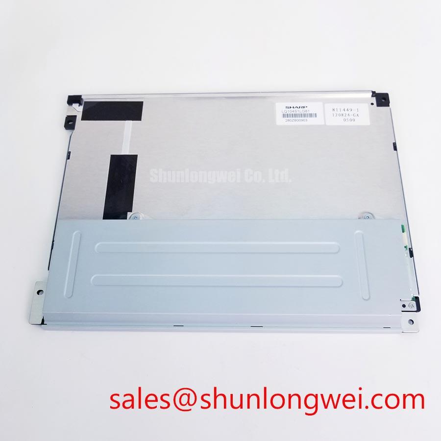
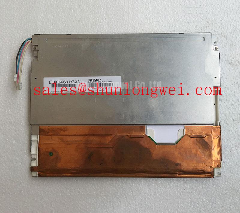
Heat around the narrow edges of an industrial display assembly should be assessed at the enclosure level rather than assumed from the LCD module alone. The LQ104S1DG61 is supplied as a TFT LCD display module, but the available factory identification data does not define an approved heat spreader geometry, thermal interface material, backlight technology, brightness retention curve, or operational life figure. These items should therefore be verified from the original equipment documentation and the complete display assembly design.
Design Consideration: when an operator terminal has restricted enclosure airflow or nearby heat generating electronics, an aluminum rail or heat spreading feature can help distribute localized thermal loading along the chassis structure. The rail must not bear directly on the active viewing area or create an edge load that transfers through the bezel into the LCD stack. Thermal interface placement should support heat transfer while preserving a mechanically neutral mounting condition.
During a service inspection, examine whether the panel perimeter remains flat after the retaining frame is secured. Look for edge brightening, dark zones, pressure related mura, or image changes that appear after the enclosure reaches operating temperature. Such observations do not establish a single root cause, but they can indicate that mechanical compression, internal heat accumulation, external illumination, or an unstable display drive condition requires further review.
A maintenance team evaluating long term brightness behavior should avoid assigning a life expectation to this model without the applicable factory optical specification. Any discussion of L70, B50, backlight current, or decay curves belongs to the verified backlight and driver assembly, not to an assumed configuration. Where a separate display solution must be reviewed for system compatibility, the LQ9D03B can be assessed independently against the original machine interface and mechanical requirements.
For Zone 2 operator station assemblies, heat management also intersects with the certified enclosure arrangement. The display module itself should not be represented as providing explosion protection, ingress protection, or system level safety certification. The system integrator must validate the complete enclosure, thermal path, cable entry method, and permitted equipment arrangement against the requirements governing the installed station.
Industrial Bezel Mechanical Envelope Tolerances & Mounting Screw Torque Optimization
Mount the LQ104S1DG61 only after checking that the bezel aperture does not contact the active display region and that the mounting frame supports the module evenly around its intended fixing points. A warped front panel, uneven gasket thickness, or fasteners tightened in sequence from one corner can produce localized stress. In service, that stress may become visible as uneven luminance, edge pressure marks, or image nonuniformity when the panel is viewed against a uniform background.
Design Consideration: where an M3 fastening scheme is used by the host equipment, a cross pattern and a controlled torque process help distribute clamping force. The commonly used 0.35 to 0.45 N·m range is a general mounting starting reference for suitable M3 hardware, not an official Sharp torque specification for this display module. The final torque, washer arrangement, thread engagement, bezel tolerance, and gasket compression must be determined by the system mechanical design and verified on the finished assembly.
Do not treat a gasket as a simple dust barrier. Its material condition, compression uniformity, and compatibility with the industrial enclosure influence both sealing behavior and the loading applied to the display perimeter. Inspect older stations for hardened, displaced, torn, or permanently compressed gasket material. If the enclosure has been opened repeatedly, verify that the front frame closes without twisting the panel or trapping the display cable.
⚠️ Maintenance Note: Disconnect equipment power and follow the station service procedure before releasing a display cable or loosening the bezel hardware.
Condensation management should also be addressed at enclosure level. A panel replacement does not correct moisture entering through damaged seals, poorly managed cable entries, or inadequate thermal control during cold starts. If moisture marks, intermittent image behavior, or corrosion are present, inspect the complete front door and internal environment before placing a replacement display into service.
For organizations comparing replacement candidates, interface verification should come before a physical size comparison. The LMS700KF01-001 is a separate display product that can be reviewed as part of a controlled compatibility assessment. Engineers should verify the original panel documentation, mounting envelope, connector position, signal format, supply requirements, and controller firmware support before considering any substitution.
Suppressing Pixel Jitter & Horizontal White Lines Potentially Associated with Adjacent 400V Motor Drives
When pixel jitter, horizontal white lines, unstable colors, intermittent blanking, or periodic noise bands occur near a variable frequency motor drive, begin by separating visual symptoms from presumed causes. Confirm whether the issue follows motor switching activity, display cable movement, cabinet door position, grounding changes, temperature, or the particular controller board installed. Compare the affected signal path with a known good path where this can be done safely within the equipment maintenance procedure.
Engineering Recommendation: preserve a continuous shield termination strategy for the display cable where the equipment design calls for shielding. The cable shield, connector shell, chassis bonding arrangement, and routing near power conductors should be reviewed as one path. A shield connected only in a way that is inconsistent with the original enclosure design can leave common mode interference unresolved. Cable routing should minimize coupling with motor output conductors and switching power paths, with final performance confirmed by measurement on the operating system.
Ferrite suppression can be evaluated where conducted or radiated interference is suspected, but it is not a universal repair. Its material, placement, and effectiveness depend on the cable, frequency content, grounding topology, and source impedance. Fitments should be tested for image stability and for any unintended effect on the display interface. The original panel documentation must be used to confirm the interface type and signal requirements for the LQ104S1DG61; the available factory identification information does not authorize an assumed LVDS pinout, differential impedance, skew budget, or power sequencing profile.
Cold environments deserve a separate check. Slower visual response can occur in LCD assemblies at reduced ambient temperature, but the available official data provided for this module does not state an operating temperature range, response time curve, heater requirement, or heater control method. If the operator station uses a heater strip or thermostatic strategy, verify it against the original system drawings and ensure that it does not create local pressure, unwanted condensation cycles, or an unvalidated thermal condition at the panel edges.
Technicians working on high noise industrial HMI systems can use the Industrial Display & HMI Solutions engineering guide as a reference point for broader enclosure, cabling, and environmental evaluation. The final acceptance criterion should be stable performance in the actual machine configuration, including normal motor drive operation and the intended cabinet grounding arrangement.
Optical Luminance Degradation Curve & CCFL to LED Modernization Retrofit Pathways
Do not classify the Sharp LQ104S1DG61 as CCFL or LED backlit unless that configuration is confirmed by its original factory documentation. The verified product information identifies the unit as a TFT LCD display module, but it does not provide a backlight technology, lamp count, LED arrangement, inverter voltage, driver current, PWM dimming range, acoustic performance, or brightness half life rating. These details must be established before a repair plan or modernization proposal is approved.
A brightness complaint should first be evaluated through observable evidence. Compare display output with the original controller settings, inspect the display cable and power connections, check for contamination at the viewing window, and review whether the issue changes with temperature or enclosure state. A dim image can relate to multiple conditions across the LCD module, optical stack, backlight assembly, power supply, dimming control, controller board, or protective enclosure. Component replacement should follow documented electrical and mechanical verification rather than a single symptom based assumption.
Design Consideration: a conversion from a legacy illumination system to a different backlight architecture changes more than light output. It can affect power distribution, dimming behavior, thermal loading, display controller compatibility, protective fault behavior, cable routing, and enclosure approval. A retrofit path should be treated as a complete system engineering change. The integrator should verify the required supply voltage, control interface, fault reporting arrangement, optical performance, and mechanical clearance from original equipment documentation before introducing a different illumination or driver solution.
Similarly, anti glare and anti reflective surface treatments must not be presumed for this model without a confirmed optical specification. Surface cleaning should use materials approved by the equipment manufacturer and should avoid introducing abrasion, residues, or stress at the panel edges. If a front protective window is used in the operator station, review the display and window as an optical pair because reflected ambient light, viewing angle, internal spacing, and contamination can alter apparent contrast.
Where touchscreen function is part of the finished HMI, it should be assessed as a separate layer or assembly unless the original documents specifically define it as integral to the LQ104S1DG61. Glove operation, water tolerance, touch sensitivity, and control firmware behavior are system characteristics that require validation on the finished operator station. This approach keeps the replacement decision tied to confirmed panel identity and verified machine level requirements.