Content last revised on September 10, 2026
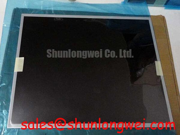
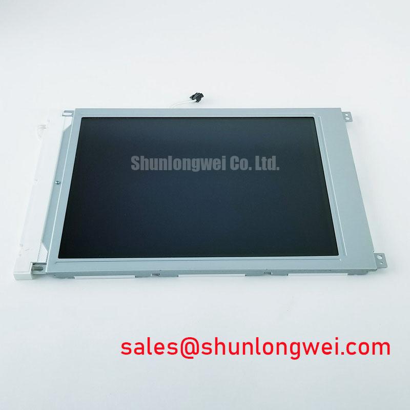
Bench-level inspection of the AUO M185XW01 V1 must begin by verifying pin-to-ground cold impedance across the 30-pin LVDS interface connector before applying external power, confirming that no DC shorts exist along the logic supply rail. Rated for an operating logic supply voltage of VDD = 5.0 V (Official Datasheet Specification), this 18.5-inch transmissive TFT panel requires precise electrical and mechanical integration protocols to maintain operational reliability when deployed in demanding industrial environments.
Mitigating Gray-to-Gray (GTG) Response Time Escalation during Cold-Start Machine Power-Up
The AUO M185XW01 V1 features a native 1366 x 768 (WXGA) screen resolution with an active display area measuring 409.8 x 230.4 mm (Official Datasheet Specification). The panel operates across a specified temperature boundary of 0 to 50 °C with storage limits from -20 to 60 °C (Official Datasheet Specification). In cold-start scenarios where ambient temperatures hover near the 0 °C lower operating threshold, nematic liquid crystal fluid exhibits a pronounced rise in dynamic viscosity. This physical shift restricts the rotational velocity of the liquid crystal directors under electric field excitation, resulting in prolonged Gray-to-Gray (GTG) state transitions that manifest visually as image smearing, ghost trails, or delayed character updates on dynamic status screens.
To evaluate these cold-start phenomena, engineers must account for how drive timing margins interface with slower liquid crystal relaxation times. The panel relies on a 1-channel, 8-bit LVDS interface running a nominal pixel clock frequency designed for 60 Hz frame synchronization. At lower temperatures, the electrical propagation delay through the source and gate driver ICs shifts, requiring the host graphics controller to provide stable differential clock jitter margins and conservative data setup and hold windows. Integration teams evaluating alternative generational revisions within this form factor often review the M185XW01 VE to compare drive timing tolerances and signal handling characteristics across varying thermal states.
A deeper examination of liquid crystal cell physics under fluctuating environmental conditions is detailed within The Ultimate Guide to Industrial TFT LCD Technology. System designers must ensure that peripheral heating or controlled pre-heat cycles bring the panel surface above 0 °C prior to demanding high-frame-rate operator interactions, preserving liquid crystal alignment stability and protecting perimeter epoxy seal integrity from cyclic micro-stresses induced by rapid, uneven thermal transitions.
Thermal Expansion Clearance Sizing across Heavy Industrial Metal Enclosure Cutouts
Mechanical mounting of the AUO M185XW01 V1 into rigid industrial enclosures requires strict adherence to physical dimensions and mechanical isolation rules. The display features an overall outline dimension of 430.37 x 254.6 x 16.5 mm (Official Datasheet Specification). In heavy-duty deployments, such as an operator console designed for a Hazardous Petrochemical Zone-2 Explosion-Proof Operator Station, displays are mounted within heavy cast-aluminum or milled stainless steel housings. Because the thermal expansion coefficient of industrial structural metals differs significantly from the sheet-metal and polymer composite frame of the LCD module, mechanical cutouts must provide calculated expansion gaps along both horizontal and vertical axes.
Rigidly clamping the outer bezel of the module induces localized compressive stresses across the internal optical stack. When the outer frame twists or experiences uneven torque, mechanical pressure transfers directly through the front polarizer to the liquid crystal cell gap, creating dark-field optical non-uniformity known as mechanical mura. Fasteners securing the module brackets should adhere to a controlled cross-pattern torque limit (Design Consideration: 0.35–0.45 N·m for standard M3 hardware) combined with compliant silicone or elastomeric spacers to distribute clamping forces evenly without pinching the chassis perimeter.
| Parameter | Official Datasheet Specification | Unit / Engineering Condition |
|---|---|---|
| Screen Diagonal | 18.5 | Inches (47.0 cm) |
| Native Resolution | 1366 x 768 (WXGA) | Pixels (16:9 aspect ratio) |
| Luminance | 300 | cd/m² (Typical, center point) |
| Contrast Ratio | 1000:1 | Typical (Transmissive mode) |
| Viewing Angles (L/R/U/D) | 85 / 85 / 80 / 80 | Degrees (Typical, CR ≥ 10) |
| Backlight Configuration | CCFL (2 lamps) | 50,000 Hours (Minimum lifetime at 25 °C) |
| Logic Supply Voltage (VDD) | 5.0 | Volts DC (Typical) |
| Interface Topology | LVDS (1 channel, 8-bit) | 30-pin internal interface connector |
| Active Area Dimensions | 409.8 x 230.4 | mm (Width x Height) |
| Module Outline Dimensions | 430.37 x 254.6 x 16.5 | mm (Width x Height x Depth, Max) |
| Operating Temperature Range | 0 to 50 | °C (Operating surface temperature) |
Diffuser Film & Prism Sheet Thermal Buckling Prevention under Continuous Full-Duty Operation
The backlight system of the AUO M185XW01 V1 utilizes a dual-lamp Cold Cathode Fluorescent Lamp (CCFL, 2 pcs) architecture, delivering a typical surface luminance of 300 cd/m² and a static contrast ratio of 1000:1 with viewing angles spanning 85/85/80/80 degrees (Official Datasheet Specification). The lamps are rated for a minimum operational lifetime of 50,000 hours under standard drive current conditions (Official Datasheet Specification). Unlike solid-state LED arrays, CCFL assemblies operate at high striking and running AC voltages, generating localized heat concentrations along the edges of the light guide panel (LGP).
Under continuous 24/7 duty cycles, heat dissipated along these lamp chambers conducts into the optical film stack, which includes bottom diffusers, brightness enhancement prism sheets, and reflective polarizers. If internal chassis ventilation is inadequate or if external thermal paths are blocked, localized thermal gradients cause internal polymer sheets to expand non-uniformly. This expansion produces internal film buckling or warping, seen by the end user as subtle horizontal wave patterns or localized color temperature shifts across the active screen area.
System designers integrating CCFL-based display panels must incorporate sufficient heat sinking along the lamp housing edges to conduct thermal energy away from the optical cavity toward the outer enclosure. When planning platform maintenance or evaluating display subsystems across legacy production lines, engineers often compare inverter and display module configurations against complementary units such as the LM190E08-TLG6, allowing technicians to verify inverter strike voltages, tube current ratings, and wiring clearance layouts before final field deployment.
Logic Supply Voltage Sequencing (3.3V/5.0V) to Eliminate Driver IC Latch-Up Risks
The digital interface of the AUO M185XW01 V1 requires strict adherence to power sequencing boundaries to safeguard the timing controller (T-CON) and row/column driver integrated circuits. Operating on a nominal 5.0 V logic bus, the module demands that supply voltage rise times satisfy specified power-on ramp windows (Design Consideration: 0.5 ms < t1 < 10 ms) before differential signaling begins. Applying high-frequency LVDS data signals while the 5.0 V logic rail remains in an indeterminate low-voltage state forward-biases the internal ESD protection diodes of the input pins, potentially triggering a low-impedance thyristor latch-up condition that can permanently damage the T-CON silicon.
💡 Pro Tip: Maintain strict length-matching across the single-channel LVDS data pairs and differential clock lines to suppress high-frequency skew and prevent horizontal line tearing during rapid video refresh.
The single-channel 8-bit LVDS bus consists of four differential data pairs (RxIN0-, RxIN0+ through RxIN3-, RxIN3+) and one differential clock pair (RxCLKIN-, RxCLKIN+). Transmission lines on the carrier interface PCB must be routed as 100-ohm differential controlled-impedance pairs. System integrators must also verify the correct format mapping between the host graphics driver and the panel interface. Mismatching standard VESA 8-bit mapping with JEIDA bit alignment will cause the most significant bits (MSB) and least significant bits (LSB) to transpose, resulting in severe color contouring, washed-out palettes, or static noise across intermediate gray levels.
During shutdown, the host controller must follow the reverse sequence: disable high-speed LVDS signal transmission, allow the differential lines to settle to zero potential, and then ramp down the 5.0 V logic supply rail. Adhering to these power-down sequences ensures internal shift registers clear without trapping floating gate charges, eliminating momentary image retention or screen flashes when the unit is de-energized.