

Content last revised on September 24, 2026
Aluminum Heat Spreader Sizing & Thermal Interface Placement along Narrow Display Edges
Inspect the replacement unit for connector damage, glass-edge impact, frame distortion, and visible contamination before connecting it to a high-voltage substation protection or SCADA console. Confirm the panel marking against DMF-50260NF-FW-15, then compare the original system documentation for supply requirements, interface format, backlight control, and mechanical clearances.
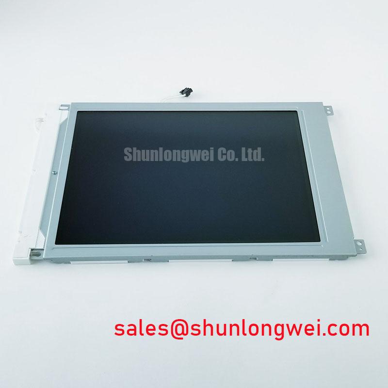
The Kyocera / OPTREX DMF-50260NF-FW-15 is an industrial-grade LCD/HMI panel supplied as a TFT-LCD display module. The available factory information identifies the product category, manufacturer, enclosure format, and official specification status, but it does not provide a complete public electrical pinout, active-area drawing, optical specification, backlight rating, or timing table. Those values should be confirmed from the original panel documentation or the equipment manufacturer before installation.
For procurement and repair work, the principal compatibility question is not only whether the glass fits the enclosure. The replacement assessment should also cover the T-CON relationship, grayscale and gamma behavior, interface signaling, backlight driver compatibility, cable routing, mounting pressure, and the viewing environment. Kyocera’s industrial display technology background can be reviewed through the Kyocera Industrial TFT-LCD Display Technologies reference. The linked information should be treated as manufacturer technology context rather than as a substitute for the specific documentation of this model.
| Model | DMF-50260NF-FW-15 |
| Manufacturer | Kyocera / OPTREX |
| Product category | Industrial Grade LCD/HMI Panel |
| Package or enclosure | TFT-LCD Display Module |
| Specification status | Official Factory Spec Verified |
Aluminum Heat Spreader Sizing & Thermal Interface Placement along Narrow Display Edges
Begin thermal integration by mapping heat sources around the display opening rather than placing a metal rail against the glass by assumption. In a compact SCADA or protection-console enclosure, local heating may come from the backlight driver, nearby processor boards, regulators, or restricted airflow. Measure the temperature distribution of the complete assembly under representative brightness and enclosure conditions, then determine whether a heat spreader rail is required along a narrow edge.
This is a Design Consideration, not a factory rating for the DMF-50260NF-FW-15. An aluminum spreader should contact the intended chassis or structural path through a controlled interface while avoiding pressure on the glass, polarizer, flex circuit, or connector area. The rail profile, contact area, and fixing method remain system-dependent. Designers should verify that the mechanical interface does not introduce frame bowing or concentrated stress during thermal cycling.
Backlight uniformity should be evaluated at the same time. A long-life display assembly depends on stable thermal distribution across the light-emitting and optical regions, but the supplied data does not confirm the backlight technology, LED board construction, optical film stack, or L70/B50 performance for this model. Do not transfer a lifetime claim from another Kyocera or OPTREX panel. Instead, inspect brightness uniformity at low, nominal, and high operating settings and compare the result with the original display.
The host electronics also require signal integrity review. If the original assembly uses an LVDS interface, the replacement cable and receiver network should be checked for differential routing, termination, return-current continuity, and connector orientation. A 100 Ω ± 10% differential target may be used as a general high-speed interface design consideration where it matches the transmitter and receiver documentation; it is not an asserted factory specification for this display. If the equipment uses TTL signaling, the system integrator should verify logic levels and pin assignment from the original documentation rather than assuming LVDS compatibility.
💡 Pro Tip: Keep the display cable away from high-current switching conductors and verify pixel-clock quality at the panel connector when intermittent noise appears only under load.
Polarizer Durability & Optical Retardation Film Inspection under Direct Industrial Lighting
Inspect the front surface with the module unpowered and under oblique illumination. Look for scratches, pressure marks, edge lifting, contamination, and irregular reflections that could become visible when the display is viewed from the operator position. Surface appearance should be assessed through the installed cover window as well as on the bench, because anti-glare behavior and contrast can change when the enclosure introduces reflections or a protective overlay.
The available factory information does not confirm whether the panel uses TN, IPS, MVA, or another liquid-crystal mode, and it does not publish a specified viewing cone, retardation-film construction, haze value, or anti-glare treatment for this exact model. A repair engineer should therefore avoid assigning a viewing-angle figure or optical film material without the panel datasheet. Under direct substation-room lighting, inspect black, white, and mid-gray screens from the actual operator eye position and check whether reflected light obscures alarm text or trend graphics.
Grayscale performance should be checked through the complete T-CON and host signal path. Gamma correction is determined by the panel electronics and its drive settings, so a replacement can appear electrically active while still producing incorrect mid-tone separation, crushed blacks, or uneven transitions. Compare a controlled grayscale pattern with the known-good unit, then review the host timing configuration, pixel format, and any programmable gamma settings available in the equipment.
Data-format alignment is equally important. The system integrator should verify whether the source uses JEIDA or VESA bit ordering, the number of LVDS data lanes, pixel-clock polarity, color depth, and display enable behavior. For a TTL interface, verify the complete signal map and logic thresholds from the original documentation. Do not infer compatibility from connector shape alone. Clock jitter and data hold performance should be checked over the equipment’s operating temperature window using the actual transmitter, cable, and receiver combination.
Kyocera’s published display information provides useful background for industrial TFT-LCD evaluation, but the DMF-50260NF-FW-15-specific optical limits, contrast data, response time, and environmental ratings must come from applicable model documentation. When the panel is installed behind a window, assess the combined effect of cover reflections, viewing angle, polarizer orientation, and ambient illumination rather than evaluating the bare module only.
Preventing Frame Lag & Image Smearing in Cryogenic Storage & Outdoor Industrial Facilities
When a display is considered for an outdoor cabinet, cold room, or other low-temperature location, test the complete module after temperature stabilization rather than relying on room-temperature appearance. Liquid-crystal viscosity, backlight output, cable flexibility, connector contact behavior, and the timing response of the host electronics can all influence moving-image clarity. The available official information for this model does not establish a cold-start limit, operating temperature range, gray-to-gray response specification, or thermal-cycle qualification.
Use moving grayscale and scrolling-character patterns to compare frame response at the intended operating conditions. Observe whether the symptom follows the panel, the video source, or the cable assembly. A slow transition may be associated with panel temperature, drive timing, source configuration, or a signal-integrity issue, so the diagnosis should be based on comparative testing rather than a single visual symptom.
Power sequencing should be reviewed before connecting a replacement. The original documentation should define the order and timing relationship of logic supply, backlight enable, display enable, reset, and video data where applicable. The system integrator should verify the required supply voltage from the original panel documentation. Do not apply a presumed voltage simply because another TFT-LCD module uses the same connector style.
For a console exposed to repeated temperature changes, inspect the bezel, gasket, cable bend region, connector retention, and panel mounting points after cycling. Sealant compatibility and enclosure sealing are system-level concerns; the model information supplied here does not verify a particular perimeter adhesive, epoxy compound, ingress rating, or outdoor qualification. Designers should validate condensation control and mechanical stress with the actual cabinet and mounting arrangement.
A replacement display may also reveal a host-side timing mismatch that was hidden by the original unit’s tolerance. Check the source timing against the panel documentation, including horizontal and vertical periods, pixel clock, data enable behavior, and synchronization method. Oscilloscope measurements at the panel connector can help distinguish a timing configuration problem from a degraded cable or receiver path. Any clock-margin conclusion should be based on the known-good assembly and the specified limits of the actual interface devices.
Full-Screen Primary Color AOI Screening: Stuck Sub-Pixels & Background Uniformity Audit
Perform a controlled visual inspection before final mechanical installation. Display full-screen red, green, blue, white, black, and mid-gray images, allowing the host system to reach its normal operating state. Record fixed bright points, dark points, vertical or horizontal lines, edge shading, flicker, and areas that change appearance when the cable is gently repositioned without applying force to the connector.
The first inspection stage should separate pixel defects from general illumination nonuniformity. A defect that remains in the same screen coordinate across multiple primary colors may require pixel or panel-level investigation, while broad brightness variation should be assessed against the original module and the enclosure’s optical conditions. These observations are diagnostic indicators, not definitive proof of a particular internal failure mode.
For the second stage, inspect the black screen in a dimmed environment and use an oblique flashlight observation from approximately the operator’s viewing direction. This can reveal localized shadowing, surface contamination, cover-window reflections, or uneven optical output that is difficult to see on a white screen. Avoid pressing the glass or rubbing the polarizer, since mechanical contact can create a temporary or permanent optical mark.
The third stage is an interface and drive-path check. Confirm the image data format, lane order, connector seating, backlight control, and T-CON behavior with the original system configuration. If a line defect or unstable region changes with signal activity, compare the waveform and continuity of the known-good path before attributing the issue to the panel glass or chip-on-glass assembly. A visual line alone does not establish a specific micro-fracture diagnosis.
Uniformity records are valuable for maintenance because they provide a baseline for later comparison. Photograph the same test patterns with fixed camera position and controlled lighting, then document the host settings and installation condition. For high-EMI equipment, maintain a continuous return path and keep differential routing symmetrical where the interface documentation requires it. Any target impedance, skew limit, or timing margin must be selected from the transmitter, receiver, cable, and display documentation as a complete system.
For broader integration guidance covering industrial display selection, enclosure concerns, interface evaluation, and HMI service planning, consult Industrial Display & HMI Solutions. The DMF-50260NF-FW-15 remains suitable for evaluation as an industrial TFT-LCD replacement only after the original equipment’s electrical, optical, mechanical, and environmental requirements have been matched against the applicable documentation.