

Content last revised on October 19, 2026
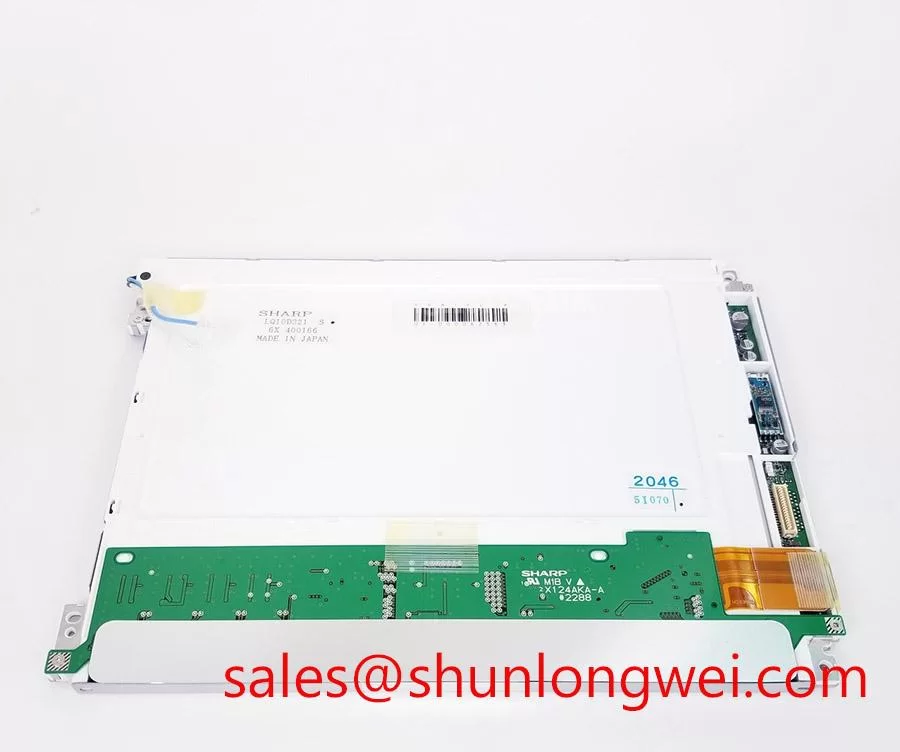
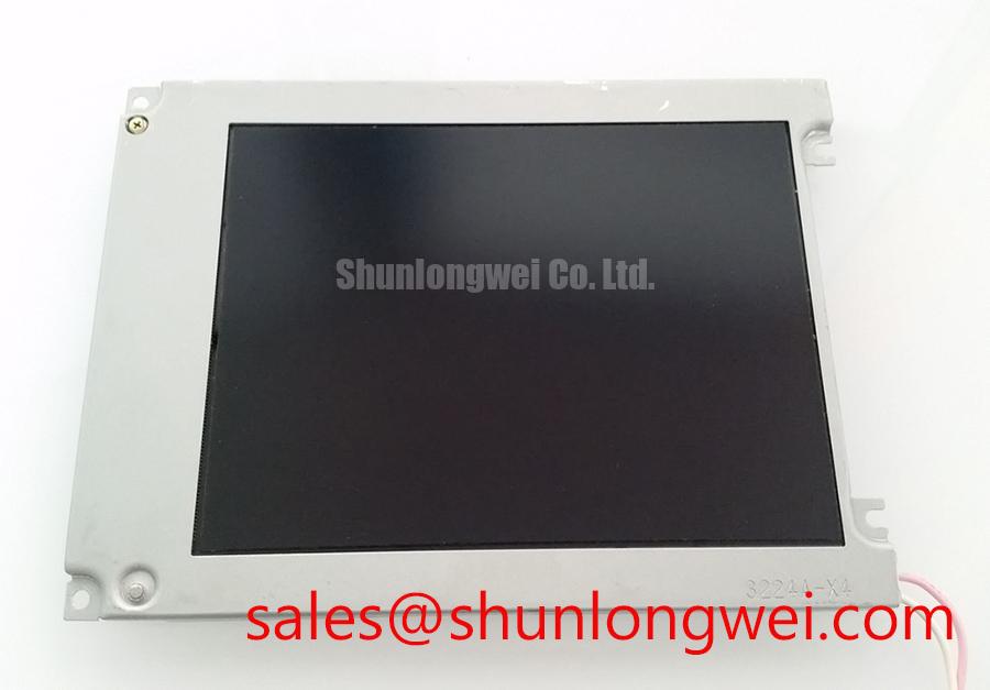
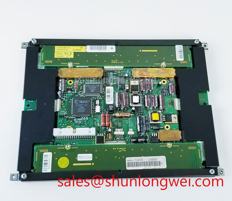
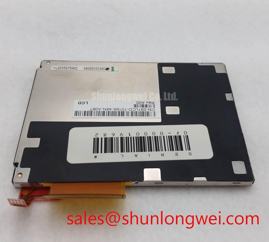
Manufacturer: Sharp | Model: LQ035Q7DH02 | Class: Industrial Grade LCD/HMI Panel | Display Type: TFT-LCD Active Matrix Color Display Module | Specification Status: Decoded Baseline / Standard Form Factor
Optical Luminance Degradation Curve & CCFL-to-LED Modernization Retrofit Pathways
When a railway passenger information display or cab signalling terminal shows a dim image, uneven brightness, delayed ignition, or an audible backlight buzz, first separate the LCD optical path from the backlight assembly. The LQ035Q7DH02 is identified here as a Sharp TFT-LCD active matrix color display module; the supplied product data does not establish a specific CCFL voltage, LED configuration, luminance rating, or backlight lifetime for this model.
A replacement assessment should therefore begin with the original panel documentation and the installed backlight wiring. A cold-cathode fluorescent lamp retrofit involves a high-voltage ignition circuit, while an LED modernization uses a regulated current driver and a compatible dimming interface. These are different electrical architectures. Reusing the original inverter output with an LED assembly, or connecting a legacy CCFL lamp to a constant-current LED driver, can produce unstable illumination and may damage the backlight circuit.
For an LED conversion, the system engineer should evaluate current regulation, enable timing, dimming polarity, connector pin assignment, thermal dissipation, and optical uniformity. A proposed 1000:1 PWM dimming capability or a 50,000-hour half-brightness target belongs to the selected LED and driver assembly, not to the confirmed baseline specification of the Sharp panel. The practical test is to record brightness at the required operating points, inspect for flicker with a suitable measurement method, and compare the result after thermal stabilization.
Acoustic noise near a display should be traced to the inverter, magnetic components, mounting resonance, or PWM interaction rather than assigned automatically to the LCD cell. If the installed system is being modernized, the backlight driver should be assessed as a complete electrical and mechanical subsystem. The TX26D200VM2BAB may be reviewed as a related display-system reference when checking driver topology and panel compatibility, but it should not be treated as an automatic substitute for the Sharp unit.
Shielded FFC/FPC Flat Flexible Cable Grounding across 360-Degree Connector Shells
Pixel jitter and horizontal noise bands are best investigated at the cable and connector interface when the display operates near variable-frequency motor drives or other high-noise equipment. Confirm that the replacement cable matches the original contact orientation, exposed-contact direction, pitch, length, and locking arrangement before applying power. The LQ035Q7DH02 product data supplied for this page does not define a confirmed LVDS pinout or connector shell construction.
A shielded FFC or FPC arrangement should provide a controlled return path around the signal interface rather than leaving the cable shield floating at one end without a defined system strategy. In a 360-degree connector-shell arrangement, the shield termination should be mechanically continuous where the enclosure and cable design support it. Grounding decisions remain system-dependent: the engineer must evaluate chassis bonding, signal reference, protective-earth architecture, and the possibility of circulating currents.
Differential routing should preserve pair symmetry and avoid sharp changes in spacing near the panel connector. A 100 ohm differential target with a 10 percent tolerance and a 50 ps skew budget are common high-speed interface design considerations, not confirmed Sharp specifications for this model. The final values must follow the display controller, cable construction, and interface documentation used in the equipment.
During troubleshooting, compare the suspect display path with a known-good cable while observing the differential waveform at the receiving interface. Look for common-mode movement, ringing, intermittent connector contact, and noise that changes with motor speed or inverter switching. Ferrite suppression can help in some installations, but its impedance profile, placement, and effect on signal integrity must be validated rather than added as a universal remedy.
⚠️ Maintenance Note: Isolate system power before disconnecting or inserting the FFC/FPC, and inspect the connector latch and cable stiffener during every service intervention.
Grayscale Inversion Mitigation & Optimal Viewing Direction Alignment
Viewing-direction testing should be performed from the actual operator position, not only from a perpendicular bench position. A normally white TN panel can show grayscale inversion, contrast loss, or color shift when viewed away from its preferred axis. The LQ035Q7DH02 listing identifies the display as a TFT-LCD active matrix color module, but the supplied official parameter set does not confirm TN, IPS, MVA, viewing angles, contrast ratio, or anti-glare surface treatment.
For a cab signalling display, mark the expected eye position and evaluate critical symbols, warning colors, and grayscale transitions from the intended seated and standing viewpoints. If the screen is installed behind a bezel or protective window, repeat the test through the complete assembly because window reflection, cover spacing, and viewing angle can alter perceived contrast.
An 85°/85°/85°/85° symmetric viewing-cone value should not be assigned to this model without a supporting Sharp datasheet. That type of specification is often associated with wider-viewing-angle panel technologies and cannot be inferred from the product category alone. If the existing equipment requires wide-angle performance, the system integrator should compare the original optical specification, viewing direction, controller compatibility, and mechanical envelope before considering another panel technology.
Surface treatment also matters under strong ambient illumination. Anti-glare etching can reduce reflected highlights, but it may change perceived sharpness and black-level appearance. The display should be evaluated inside the actual front bezel with the intended lighting, cover glass, and cleaning method. Sharp’s Industrial Display Solutions resource provides useful manufacturer-level context for industrial display and optical evaluation.
Industrial Bezel Mechanical Envelope Tolerances & Mounting Screw Torque Optimization
Mechanical replacement work should begin by measuring the original cutout, bezel contact points, connector clearance, and fastener locations before the LQ035Q7DH02 is installed. The supplied product information confirms a standard-form-factor TFT-LCD module but does not provide confirmed external dimensions, mounting-hole tolerances, screw size, or approved fastening torque.
Uneven clamping can transfer local stress into the display stack and create pressure marks, dark-field nonuniformity, or visible optical mura. The bezel should support the intended mounting surfaces without forcing the panel into alignment. Cross-pattern tightening is a useful design consideration for distributing load, while the actual fastener torque must be taken from the equipment chassis and panel assembly documentation. A value such as 0.35–0.45 N·m should not be presented as an official LQ035Q7DH02 limit without manufacturer support.
Check that gaskets contact continuously around the opening and that no cable, spacer, or burr creates a local pressure point. In dusty or humid equipment, the sealing interface should be inspected for compression loss, contamination, and gaps after service. Optical bonding, protective windows, and enclosure sealing are system-level construction choices; they should be validated for condensation, cleaning chemicals, thermal expansion, and service access rather than assumed from the LCD part number.
Direct sunlight testing should use the complete installed assembly. A contrast target above 500:1 at 50,000 lux is an application requirement that may be relevant to a high-illumination railway display, but it is not a confirmed specification for this Sharp module. Engineers evaluating a replacement should measure readability, reflected glare, backlight stability, and temperature behavior with the actual display controller and enclosure.
For a broader installation review covering sealing, optical integration, and industrial HMI service practices, consult Industrial Display & HMI Solutions. When the original panel is unavailable, the TX18D203VM2BAA can be evaluated as a separate same-class display option, subject to a full electrical, optical, connector, and mechanical compatibility check.