


Content last revised on September 10, 2026
Optical Luminance Degradation and Backlight Retrofit Assessment
Start a dim screen investigation by separating image generation from illumination. In a controlled service check, inspect whether a faint image remains visible when the front surface is viewed under external light. A visible but unilluminated image can direct attention toward the original backlight path, its driver, related supply rails, cable contacts, or upstream control logic. A completely blank image requires broader verification of the display data path, logic power, timing signals, and host controller state.
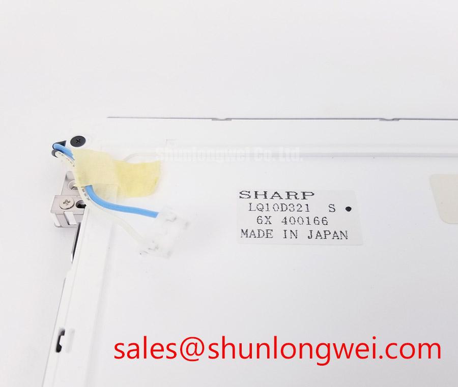
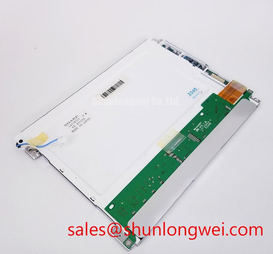
The official structured information confirms the LQ10D321 as a TFT LCD module, but it does not state a backlight technology, ignition voltage, dimming topology, luminance value, contrast ratio, optical coating, PWM ratio, or service life. These details must not be assumed from the module family name or from the appearance of a cabinet. The system integrator should verify the original panel documentation and the existing equipment schematic before evaluating any CCFL to LED conversion, driver replacement, or brightness control modification.
A backlight retrofit is a system level change rather than an inherent property of this Sharp module. Design Consideration: a retrofit review should compare the original panel’s optical stack, mechanical clearances, thermal path, dimming control method, supply architecture, and fault detection behavior. The replacement illumination assembly must be validated against the actual display enclosure rather than selected only by diagonal size or cabinet opening.
For maintenance teams assessing a related display solution in the same service workflow, LM64P10 can be reviewed as a separate display module reference. It is not a declared electrical, mechanical, optical, or interface substitute for the LQ10D321. Matchability must be established from manufacturer documents, original connector records, and bench testing.
Ambient light can make a serviceable screen appear weak even when the panel is still producing a stable image. A practical inspection compares the suspect terminal with a known working unit under similar enclosure, viewing angle, and ambient light conditions. Do not infer anti glare treatment, sunlight readability, or sustained contrast behavior for the LQ10D321 unless those properties are confirmed by the applicable Sharp documentation.
Thermal Cycling Checks for the Display Perimeter and Optical Surface
Inspect the panel perimeter, front surface, rear housing, mounting points, and attached flexible cables for mechanical stress before attributing a temperature related complaint to the LCD itself. Edge discoloration, intermittent image response, localized pressure marks, or changes after cabinet warm up can arise from multiple sources, including chassis distortion, connector contact variation, cable routing, condensation exposure, power instability, or host video timing. Each condition should be isolated through measured comparison with the original signal path.
The supplied official information does not provide an operating temperature range, storage temperature range, thermal cycle qualification, polarizer adhesive construction, perimeter sealant type, response time, or optical stability data for the LQ10D321. It is therefore not appropriate to state that the module is qualified across a particular temperature range, that it uses a specific adhesive system, or that it meets a defined low temperature response target.
Design Consideration: if a display is installed in an enclosure exposed to temperature transitions, engineers should examine enclosure sealing, airflow, heater or cooler operation, moisture management, cable strain relief, and mounting stress. Thermal behavior must be verified on the actual terminal because the panel is only one part of the display assembly. The host cabinet and front bezel can influence apparent optical defects through uneven support or pressure.
Static HMI pages also deserve a practical review. Operators often report faint retained graphics after a terminal has displayed a fixed alarm, mimic diagram, or dispatch page for long periods. This observation should be documented with images, screen content history, temperature state, and comparison against a known good display. It must not be classified as permanent image retention without controlled evaluation of the panel and the graphics controller.
For high voltage substation protection and SCADA dispatch console evaluations, technicians should keep display fault records separate from protection relay, communications, and cabinet supply faults. The broader service practices described in Industrial Display & HMI Solutions can support enclosure and integration review, while the LQ10D321 itself should be checked against its original equipment documentation.
Digital Video Interface and Logic Rail Verification at the Original Connector
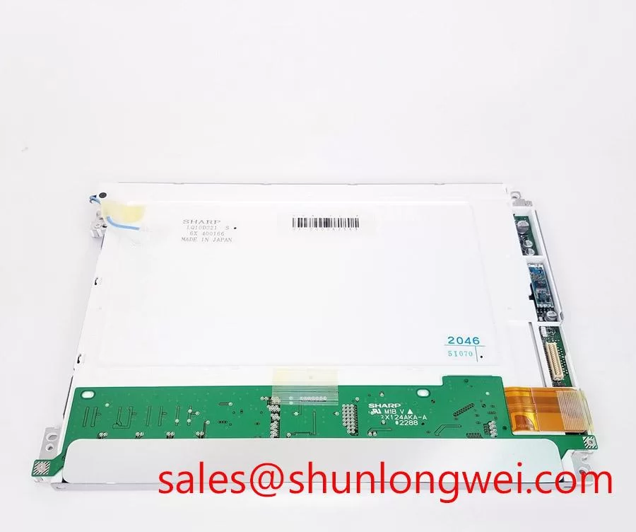
Before reconnecting the LQ10D321, photograph the connector position, keying feature, cable orientation, and any locking mechanism. Then inspect the mating harness for bent contacts, incomplete latch engagement, abrasion, and excessive tension at the point where the cable leaves the chassis. Cable movement near the connector can produce intermittent lines, color errors, unstable synchronization, or a blank screen without proving a fault inside the LCD module.
The available verified factory information does not identify the interface standard, connector pin count, pinout, logic supply voltage, video mapping, timing format, power sequencing requirement, or differential impedance requirement for this model. Do not assume TTL RGB, LVDS, JEIDA mapping, VESA mapping, a particular supply rail, or a specified power on rise time. The system integrator should verify the required supply voltage and signal definition from the original panel documentation and host controller schematic.
⚠️ Field Alert: Disconnect and reconnect the display cable only after the equipment is fully de-energized, because live insertion can expose signal pins to unintended voltage states.
A disciplined bench check begins at the host board. Confirm that the display enable state, expected video activity, supply behavior, and grounding arrangement match the known good signal path. Where test access is available, observe the waveform quality at the source and at the panel end of the cable. A difference between those points may indicate cable loss, contact resistance, grounding disruption, or impedance mismatch, and should be investigated with the system’s original electrical requirements.
Engineering Recommendation: retain the original cable routing and strain relief during replacement testing. The cable path, shielding arrangement, and chassis grounding strategy may affect signal integrity. Any interface adapter, controller replacement, or display conversion needs full functional testing for the target terminal rather than a visual power on check alone.
When evaluating a replacement display for a maintenance inventory, LM190E08-TLG6 is available as a separate product reference. It must not be treated as a direct replacement for the LQ10D321 based on product category alone. Engineers should compare the original equipment’s mechanical envelope, active display requirements, interface, power arrangement, mounting provisions, and application firmware behavior.
Chassis Fastening and Pressure Control During Panel Installation
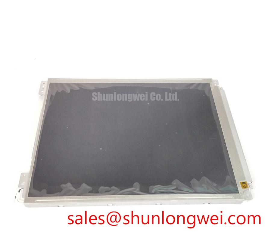
Fit the LQ10D321 into the original chassis without forcing the panel edges, rear housing, or connector cable. Before final fastening, verify that the front bezel rests evenly, no cable is trapped behind the module, and no rigid feature presses against the viewing area. Localized pressure can contribute to nonuniform appearance, temporary image distortion, or installation induced screen artifacts. These effects should be assessed with the equipment powered under normal display content after the panel is seated.
The official structured specification provided for this product does not state mounting hole dimensions, screw size, torque limit, bezel tolerance, panel thickness, or permitted compression load. Do not apply a generic M3 torque value as if it were a Sharp factory requirement for the LQ10D321. The system integrator should use the original equipment mechanical drawing or manufacturer documentation to establish screw selection, fastening sequence, and allowable clamp force.
Design Consideration: tighten panel fasteners progressively in an alternating pattern so the bezel load develops evenly. The appropriate tightening value is determined by the chassis material, fastener type, thread engagement, washer arrangement, panel support points, and original mechanical specification. After fastening, inspect the screen with dark and light test images to identify pressure related nonuniformity before returning the terminal to service.
Do not add optical bonding, gasket materials, adhesives, or spacer layers to the LQ10D321 assembly without a documented engineering review. Such modifications can alter bezel pressure, moisture paths, serviceability, heat movement, and the geometry between the display surface and touch or protective layers. If the original console includes a protective window or touch assembly, verify its stack up and support scheme before panel replacement.
For a substation protection or SCADA dispatch terminal, the final acceptance check should include normal boot behavior, stable display output, connector retention, alarm page readability, and the absence of new screen artifacts after the enclosure is closed. This verifies the installed assembly under its actual host conditions while keeping the assessment within the documented boundaries of the Sharp LQ10D321 TFT LCD display module.