Content last revised on September 10, 2026
LM190E08-TLG6 Industrial LCD Display Evaluation
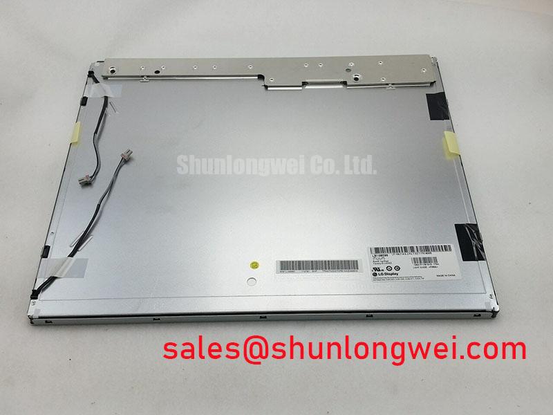
Begin the service check by comparing the installed panel label with LM190E08-TLG6, then inspect the connector area, bezel contact points, and visible glass edges before applying power. This initial verification helps prevent a mechanical or interface mismatch from being mistaken for a panel failure. The panel is identified as an LG Display 19.0 inch a-Si TFT-LCD with a TN mode, normally white transmissive operation, and an SXGA resolution of 1280(RGB) × 1024.
The official specification identifies a 5:4 horizontal-to-vertical aspect ratio, which is important when replacing a display in an industrial HMI, railway cab signalling display, or passenger information terminal. A replacement with a similar diagonal size but a different active-area ratio can create bezel interference, image scaling, or incorrect touch overlay alignment. The original system documentation should be checked for the required interface, supply arrangement, mounting envelope, and controller compatibility before installation.
| Feature | Official Specification |
|---|---|
| Manufacturer | LG Display |
| Model | LM190E08-TLG6 |
| Screen size | 19.0 inches |
| Resolution | 1280(RGB) × 1024, SXGA |
| Aspect ratio | 5:4 |
| Display technology | a-Si TFT-LCD, TN, normally white, transmissive |
| Surface treatment | Antiglare with hard coating, 3H |
| Brightness | 300 cd/m² typical |
| Contrast ratio | 800:1 typical |
| Viewing angle | 85/85/75/85 typical, CR ≥ 10 |
| Response time | 1.3/3.7 ms typical, Tr/Td |
| Display colors | 16.7 million, 6-bit plus Hi-FRC |
| Backlight | 4 CCFL lamps, 50,000 hours lifetime |
Shielded FFC/FPC Flat Flexible Cable Grounding across 360-Degree Connector Shells
For a replacement assessment, trace the complete display signal path from the host controller to the panel connector rather than testing the screen in isolation. The LM190E08-TLG6 specification provided for this product identifies the display technology and optical characteristics, but it does not establish a universal connector pinout, LVDS voltage, cable impedance, or grounding method. The system integrator should verify those details from the original panel documentation and the equipment wiring drawings.
In a cabinet located near variable frequency motor drives, switching power supplies, or long traction control harnesses, an exposed flexible cable can provide a route for common-mode interference. A Design Consideration is to maintain shield continuity around the connector entry and to bond the cable shield according to the chassis grounding architecture. A short, controlled return path can reduce the likelihood of common-mode current coupling into differential display pairs. Any ferrite component should be selected after checking the actual noise spectrum, cable construction, signal rate, and power sequencing of the host system.
Where the interface is a differential LVDS connection, designers commonly evaluate a controlled differential impedance near 100 Ω with a tolerance of ±10% and manage pair skew within the transmitter and receiver limits. These are system-level Design Considerations, not published output ratings for this panel. The correct values must be confirmed against the controller datasheet, cable drawing, and oscilloscope measurements at the panel input. Pixel jitter, intermittent horizontal bands, or unstable text may indicate impedance discontinuity, excessive common-mode noise, grounding interaction, or a controller timing problem. Compare the suspected channel with a known-good signal path before replacing the panel.
The panel should be powered down before cable insertion or removal. Inspect contacts for contamination, confirm that the locking feature is fully engaged, and avoid bending the flexible cable at the connector exit. For a railway passenger information system or cab display, the enclosure bonding, cable routing, and connector strain relief should also be checked after vibration or service access.
The related LQ201U1LW31 can be reviewed as a separate display solution in the surrounding power and interface topology. It should not be treated as an automatic substitute for the LM190E08-TLG6; electrical, mechanical, and timing compatibility remain system-specific.
Single Vertical Hairline Defect and Sub-Pixel Column Driver Open-Circuit Localization
A single vertical line should first be documented with a full-screen white, black, red, green, and blue test pattern. This multi-stage primary-color bench test helps determine whether the defect remains fixed in the same column and whether it affects every color component. Record the result at the original operating temperature and again after the assembly has reached a stable condition. A visible line that changes with cable movement, connector pressure, or controller input requires a different investigation from a line that remains fixed on every valid source.
Use an angled flashlight inspection with the panel unpowered or displaying a dark field to examine surface marks, internal shadowing, bezel pressure, and possible backlight irregularity. This is a practical isolation method, not a definitive material diagnosis. A line that follows the image data path may require checking the controller, flexible cable, and panel-side connection with approved test equipment. A defect fixed to one physical column can be consistent with a column-driver or bonded interconnect issue, but the service decision should be based on repeatable comparison testing rather than one symptom alone.
The LM190E08-TLG6 uses a TN transmissive LCD structure and a four-lamp CCFL backlight. It should not be evaluated using assumptions intended for an LED-backlit panel. A dark vertical region, uneven luminance, or delayed ignition can involve the CCFL lamp circuit, inverter, wiring, or panel optical assembly. The published 50,000-hour CCFL lifetime is an official specification reference for the backlight system; it is not a guarantee of field service life under every temperature, vibration, duty-cycle, or inverter condition.
The supplied specifications do not define a PWM dimming frequency or duty-cycle linearity for this model. If the host equipment adds PWM control to the backlight inverter, the system designer should verify the inverter’s permitted control method, frequency range, minimum operating duty, acoustic behavior, and visible flicker through bench testing. A change in brightness should be checked with a photometric method and with the actual text and graphics used by the equipment.
When the fault appears only during cold start, allow the panel and controller to stabilize while monitoring lamp ignition, image timing, and supply behavior. Cold response can be affected by the CCFL inverter and system power sequencing, so compensation should be implemented by the equipment designer only after the original timing requirements and thermal operating window have been confirmed. A display replacement should not be used to mask an unstable supply or a failing inverter protection circuit.
Aluminum Heat Spreader Sizing and Thermal Interface Placement along Narrow Display Edges
Before adding a metal rail or thermal interface material, map the actual heat sources in the enclosure. The LM190E08-TLG6 specification provides optical and backlight data, but it does not specify an aluminum heat spreader size, thermal resistance, adhesive type, or allowable bezel temperature. Any added spreader is therefore an Engineering Recommendation that must be validated against the panel frame, insulation clearances, cable routing, and service requirements.
A narrow edge rail can help distribute local heat from adjacent electronics when it is mechanically isolated from the glass and does not load the active area. The rail should have a continuous, stable contact arrangement where thermal transfer is required, while avoiding concentrated force at corners or along the display seal. Designers should verify temperature uniformity during cold start, normal operation, maximum enclosure temperature, and shutdown. The test should include the inverter and controller because the display panel is part of a wider thermal system.
The official backlight is four CCFL lamps, so claims concerning LED L70 or B50 life do not apply to this model. CCFL ignition, inverter output, lamp aging, and optical uniformity should be assessed using the original backlight architecture. If an equipment owner is considering an LED conversion, that becomes a separate engineering project involving optical matching, electrical drive compatibility, electromagnetic behavior, and mechanical changes. The original panel documentation and the conversion design must be reviewed before such a change.
Signal integrity should be checked across the intended industrial temperature range. The supplied product data does not state TTL or LVDS transmitter clock jitter, data hold time, or receiver timing margins. These values belong to the host controller and interface design. When an image becomes unstable at temperature, use a differential probe and compare clock and data timing with the controller limits. Verify that cable impedance, connector seating, supply rise time, and reset sequencing remain within the equipment design requirements.
Condensation control is equally important during a cold start. The enclosure should be assessed for moisture accumulation when a cold panel is exposed to warmer, humid air. Designers should provide an appropriate warm-up and environmental control strategy based on the actual cabinet conditions rather than assigning a universal delay to this model. Periodic inspection of air paths, sealing surfaces, and thermal interface condition can reveal a developing enclosure problem before it appears as image instability.
Industrial Display & HMI Solutions provides related engineering context for display integration in demanding equipment. It should be read alongside the original LG Display documentation and the host system’s environmental qualification plan.
Chassis M3 Fastener Torque Sizing to Reduce Optical Mura Defects
Install the panel on a clean, flat support and begin by checking that the chassis opening is free from burrs, foreign particles, and displaced gasket material. The LM190E08-TLG6 official data supplied here does not state a bezel envelope tolerance, mounting-hole pattern, M3 fastener torque, or allowable frame distortion. Those mechanical values must therefore be taken from the equipment drawing or original assembly instruction, not inferred from the electrical specification.
Uniform mechanical support is a Design Consideration because uneven compression can produce localized luminance variation, edge shadows, or visible mura. Tighten fasteners progressively in a cross-pattern where the chassis design permits it, keeping the panel aligned without forcing the glass into the opening. The appropriate torque is system-determined and should be confirmed through the original mechanical specification and an optical inspection of black, white, and mid-gray fields. A torque value suitable for one bezel, gasket, or threaded insert may be unsuitable for another.
Gasket contact should be continuous around the intended sealing perimeter, without folds, gaps, or sections that intrude into the active viewing area. Inspect the seal after the first thermal cycle and after vibration exposure because compression recovery and frame movement can alter contact pressure. The goal is to maintain environmental separation while allowing the display assembly to accommodate normal chassis tolerance and thermal expansion.
⚠️ Maintenance Note: Check the cabinet airflow path and gasket condition during scheduled service, and disconnect power before handling the display cable.
The antiglare hard coating is specified as 3H; cleaning should therefore use a method approved for coated LCD surfaces and should avoid abrasive contact. Do not press directly on the active area while checking for a line defect or bezel alignment. If the panel is installed in a railway passenger information system or cab signalling display, inspect the enclosure after shock and vibration events, then repeat the full-color image test and brightness uniformity check.
For procurement or repair evaluation, compare the panel model, screen size, SXGA timing, 5:4 format, CCFL backlight arrangement, connector configuration, and mechanical drawing as one complete set. A panel with a similar diagonal measurement is not automatically compatible. The relevant replacement assessment may include NL192108JC18-03ND, but the integrator must validate dimensions, interface, optical performance, backlight drive, and system timing before approving any substitution.