Content last revised on September 11, 2026
Wide Symmetric Viewing Cone 85°/85°/85°/85° for Multi-Angle Consoles
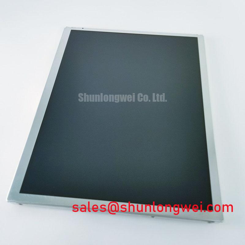
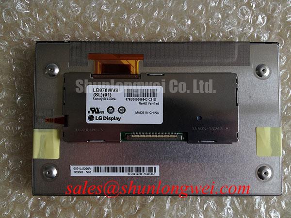
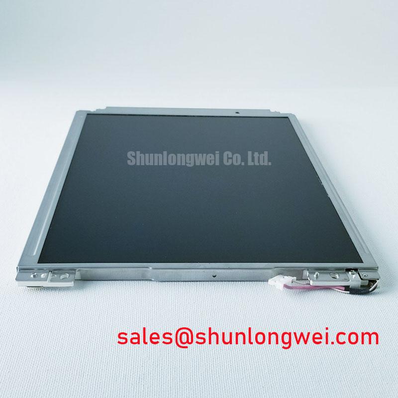
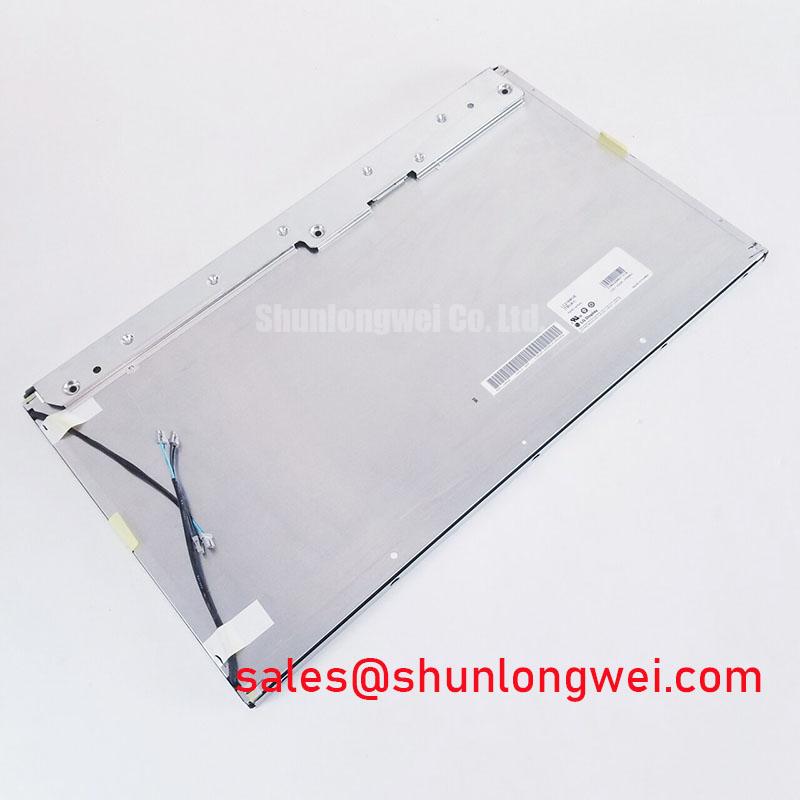
Begin service intake by checking the installed panel label against LM190E08-TLG2, inspecting the TFT LCD module frame and connector area for handling damage, then comparing the host equipment’s original panel documentation before reconnecting power. This LG Display industrial grade LCD/HMI panel should be evaluated as a complete display assembly within the original system electrical, mechanical, and optical boundaries.
For a dark or apparently blank operator terminal, first distinguish between absent image data and absent illumination. With the equipment in its approved diagnostic state, inspect whether a faint image is visible under controlled external light, confirm the panel cable is fully seated, and verify the host controller’s documented power and signal sequence. A black screen can originate in the panel supply path, backlight drive path, video path, cable assembly, controller board, or protective logic; the symptom alone does not establish one cause.
⚠️ Field Alert: Disconnect system power and allow stored energy to discharge before removing or inserting the display connector, because live handling can expose signal pins to unintended electrical stress.
The LM190E08-TLG2 is identified as an industrial grade TFT LCD display module. Where the original equipment documentation specifies a symmetric 85°/85°/85°/85° viewing cone, technicians should evaluate the replacement installation from the actual operator positions rather than from a single straight on bench view. This matters on shared consoles, where an off axis user may assess text, alarms, or status colours from a different height or side position.
Grayscale behaviour is an important practical check during screen assessment. A panel with wide symmetric viewing characteristics is intended to reduce the angle dependent tonal shift associated with conventional narrow viewing arrangements, but the complete observed result still depends on the source timing board, display settings, cover lens, ambient light, and the condition of the panel itself. Use a known good test image containing neutral grays, fine text, solid color fields, and dark transitions. Inspect from the normal operating positions specified by the equipment layout.
Surface glare must also be evaluated at the assembled equipment level. Anti glare treatment can help diffuse reflected overhead lighting, while a front cover, adhesive layer, protective window, or accumulated surface contamination can change what the operator sees. Do not infer a particular coating construction from the model number. The system integrator should confirm the original panel documentation and the host enclosure optical stack before assigning a surface performance requirement.
For digital display links, differential signal routing is a Design Consideration, not a factory rating of this module unless confirmed in the original interface documentation. Controlled differential impedance and pair to pair timing consistency help preserve the signal eye when cable routing passes through electrically noisy equipment. In a high EMI installation, the cable type, route, grounding scheme, controller output, and connector condition must be assessed together. An apparent color shift or intermittent picture should not be attributed to the LCD glass until the known good source path has been compared.
When a maintenance team is evaluating a same class panel for a legacy repair, NL192108JC18-03ND can be reviewed as a separate compatibility candidate. Its mechanical drawing, interface assignment, signal format, timing requirements, mounting arrangement, and optical requirements must be checked against the original equipment documentation. Similar display size or resolution alone does not establish interchangeability.
Evaluating Display Uniformity and Thermal Conditions under Continuous Full-Duty Operation
For continuous duty terminals, inspect the installed display perimeter, rear support structure, and the clearance around heat producing controller hardware before deciding that the panel itself is responsible for a brightness or uniformity concern. The official product identification supplied for LM190E08-TLG2 is TFT LCD Display Module; it does not authorize assumptions about internal optical films, backlight architecture, thermal materials, lifetime hours, or a specific backlight drive topology.
A localized bright or dark area can have several possible origins. Check whether the appearance changes with enclosure temperature, panel position, cable movement, supply stability, or the displayed content. Compare the affected unit with a known good assembly under the same image and lighting conditions where practical. Inspect rear brackets and edge retention for uneven pressure, but do not loosen or reshape structural parts without the equipment manufacturer’s mechanical instructions.
Heat spreader rails and chassis conduction are Design Considerations for the host equipment. Their purpose is to avoid concentrating heat near narrow display edges and to keep the enclosure thermal path consistent with the equipment’s validated design. Rail dimensions, attachment method, interface material, and allowable pressure are system determined. Engineers should verify enclosure temperatures and optical performance during representative full duty testing rather than treating a generic thermal arrangement as a requirement for this panel model.
Backlight troubleshooting should remain evidence based. Confirm the host’s documented supply rails and enable controls, inspect the cable for pin displacement or strain, and observe whether the display state changes when tested with an approved known good controller path. A backlight protection event, unstable supply, failed driver, damaged cable, or panel related issue can all produce a dim or dark presentation. Do not bridge protection circuits or force an unknown backlight supply into the module.
Where a host uses PWM control, audible noise, visible flicker, and text stability are properties of the entire driver, harness, and mechanical assembly. The original system design determines the valid dimming control conditions. During repair validation, observe the screen at several intended brightness settings and verify that the output remains stable during normal equipment operation.
Suppressing Pixel Jitter and Horizontal White Lines Induced by Adjacent 400V Motor Drives
If pixel jitter, horizontal white bands, momentary image loss, or unstable colors appear when a nearby motor drive changes state, begin by recording the exact operating condition and checking the display harness route. A 400V motor drive can be an electromagnetic noise source in an industrial installation, but the display symptom may also arise from connector resistance, a weakened controller output, supply disturbance, grounding discontinuity, incorrect timing, or cable damage.
Inspect both ends of the display cable for full engagement, damaged latch features, trapped conductors, and strain imposed by cabinet doors or moving structures. Verify that the cable route follows the original equipment practice and that it does not share an uncontrolled route with high energy motor conductors. For shielded cable assemblies, continuity and termination must be assessed against the host equipment documentation. A shield connected incorrectly can be as unhelpful as an absent shield.
Common mode suppression, connector bonding, and cable shielding are Engineering Recommendations that require system level verification. A 360 degree shield termination can be appropriate where the validated cable and enclosure design call for it, while ferrite selection depends on the measured disturbance spectrum, cable impedance, and signal behaviour. Designers should compare the display signals with a known good path using suitable instrumentation, then verify that peak noise and image stability remain acceptable in the actual equipment operating state.
Do not diagnose every white horizontal line as panel damage. First isolate the source by testing the controller output, display cable, supply rails, grounding path, and environmental trigger in a controlled sequence. If the artifact follows the cable or controller, the panel is not the first corrective target. If it remains with a verified source path and approved system configuration, the panel assembly can then be assessed within the equipment service procedure.
For broader context on LCD signal paths, optical behaviour, and selection checks, consult The Ultimate Guide to Industrial TFT LCD Technology. It is useful for framing the inspection process, while the original equipment documentation remains the controlling source for this model’s interface, electrical limits, and installation requirements.
Evaluating High-Humidity Storage Exposure and Delamination Risks
Before returning a repaired terminal to service after storage exposure, inspect the display front surface, perimeter, connector area, and mounting frame under clean, controlled light. The stated 60°C / 90% RH condition and thermal range references must be treated as application evaluation conditions unless they are confirmed by the original LG Display specification for the exact suffix and revision. Do not convert an environmental test reference into an unconditional operating or storage rating for LM190E08-TLG2.
Humidity can affect the display assembly, host enclosure, cable contacts, adhesives, and power electronics in different ways. Look for visible residue, moisture ingress indicators in the enclosure, corrosion at mating hardware, abnormal surface appearance, and intermittent connection behaviour. If exposure is suspected, follow the equipment manufacturer’s drying, inspection, and requalification procedure. Applying uncontrolled heat or opening a bonded display assembly can create additional damage and invalidate the diagnostic result.
Low temperature behaviour also requires measured verification. Liquid crystal response can appear slower as temperature falls, while an apparent lag may also involve controller timing, backlight response, power sequencing, or software refresh behavior. Use the original equipment test mode or a known good signal source, allow the complete assembly to reach the relevant test condition, and compare image transitions against an approved reference unit where available.
Claims about optical contrast under direct sunlight, anti glare coating performance, perimeter seal chemistry, and thermal cycling limits require the exact official datasheet or validated system qualification record. The system integrator should verify these requirements from original panel documentation and the equipment enclosure design, especially for AGV and forklift telematics displays exposed to changing light, vibration, and cabin conditions. A panel replacement should be accepted only after interface operation, mounting fit, image quality, and equipment level environmental performance have been checked in the intended system.