Content last revised on October 5, 2026
Chassis Fastener Pressure and Dark-Field Mura Checks
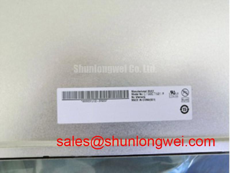
Disconnect the display supply, then inspect the LM190E08-TLG1 connector seating and chassis contact points before treating a dark screen as a failed panel. This LG Display TFT-LCD display module should be evaluated against the original equipment documentation for its electrical ratings, interface pinout, active area and mounting dimensions; a matching model label alone does not establish system compatibility.
Begin with the panel unpowered and the front bezel accessible. Look for a bowed frame, uneven gasket contact and pressure marks near mounting points. After reassembly, display a uniform dark image and inspect it from the normal operating position. A bright or dark patch that changes when bezel pressure is relieved can point toward a mechanical fit problem, but it does not, by itself, identify the panel as the failed part.
Design Consideration: Tighten chassis fasteners in a balanced sequence so the enclosure supports the module without twisting it. The acceptable fastener torque and bezel clearance must come from the equipment drawing and the applicable panel documentation; neither value is established here as an official LM190E08-TLG1 specification. Check for cable strain after the bezel is secured, particularly where a flexible lead passes close to a bracket or cover edge.
Assess contrast, glare and viewing angle under the equipment’s actual lighting rather than assigning an unverified sunlight-performance figure to this module. A display considered for an ultrasound diagnostic console or surgical navigation terminal would also require system-level evaluation of image presentation, enclosure design and applicable equipment requirements. For a separate panel comparison, NL192108JC18-03ND can serve as a reference point, but its dimensions, electrical interface and mounting pattern need independent checks before any substitution decision.
Localizing a Vertical Hairline or Dark Screen
Feed the panel known-good full-screen red, green and blue images, recording whether a vertical line stays in the same position and which test images expose it. Then compare that result with a known-good signal path. A fixed line can be associated with the panel signal path or column-drive circuitry; an intermittent line that changes when the cable is reseated can instead direct attention to the connector, cable or host output. Do not press on the display edge to force a diagnosis.
For a screen that appears black, first verify that the host is producing an image and that the display supply follows the original equipment specification. View the screen under an oblique flashlight: a faint image can help separate an illumination problem from a missing-image problem, although further measurements are needed to identify the failed assembly. Inspect the backlight power path and its control signals using the equipment schematic. The backlight technology, driver arrangement and lifetime rating must be confirmed from the relevant documentation rather than inferred from the panel model.
Field Alert: Disconnect power before unplugging or reseating the display cable.
White screens and retained images also warrant a power-sequence check. Observe panel supply, image signaling and illumination control during startup and shutdown, then compare their order with the original system requirements. This is an Engineering Recommendation, not a claim of a factory-specified delay for LM190E08-TLG1. If another display assembly is being assessed within the same service project, LQ201U1LW31 should be reviewed as a separate display solution, not assumed to be its backlight driver or a drop-in match.
Thermal Exposure, Image Response and Static HMI Content
When image transitions look sluggish after a cold start, measure the ambient and panel-area temperatures and compare them with the documented operating range before attributing the behavior to a defect. Liquid-crystal response changes with temperature as a general display characteristic, but a specific temperature range or gray-to-gray response limit should not be assigned to LM190E08-TLG1 without its applicable specification.
Inspect the enclosure for blocked airflow and heat concentrated near the display perimeter or illumination electronics. If brightness is uneven, compare the pattern after the unit reaches its normal operating condition; this helps distinguish a transient thermal effect from a persistent optical fault. Review dimming behavior at the brightness settings used by the equipment, checking for visible flicker or audible noise. Any PWM settings are determined by the verified driver and system design, not by a generic frequency prescription.
Long-running HMI pages often leave status bars, icons and controls in fixed positions. If a residual image is reported, document the displayed content and operating conditions, then retest with varied images before deciding whether the effect persists. Optical bonding, sealing performance and wide-viewing-angle behavior likewise require confirmation at the assembled-system level. Design Consideration: For temperature or environmental margin assessments, use measured conditions and the applicable panel limits; The Ultimate Guide to Industrial TFT LCD Technology provides broader context for planning those checks.
Flexible Cable Seating and Display Signal Integrity
Trace the display cable from the host board to the LM190E08-TLG1 connector, checking latch engagement, contact contamination, shielding termination and bends at enclosure transitions. A loose connection can produce intermittent images, horizontal noise or a blank screen. Replace or reroute a visibly damaged cable only after confirming its pinout and mechanical fit against the original assembly documentation.
Where the host uses a differential display interface, keep paired conductors together and preserve the intended shield and return-current path when routing the cable near motor-drive wiring. Treat shielding, ferrites and grounding as Design Considerations: their effectiveness depends on the host, cable and enclosure, and must be checked in the assembled equipment. Do not assume a particular LVDS pinout, impedance or skew allowance for this panel without a verified interface drawing.
If horizontal bands appear only while nearby equipment operates, capture the display supply and video signals during the disturbance and compare them with a quiet-condition trace. If the fault changes when the cable is moved, inspect connector retention and routing before condemning the module. Record the host board identification, cable marking and panel label together so that a repair or purchasing review can verify the complete display path rather than relying on a visual panel match.