
Content last revised on September 10, 2026
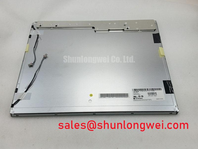
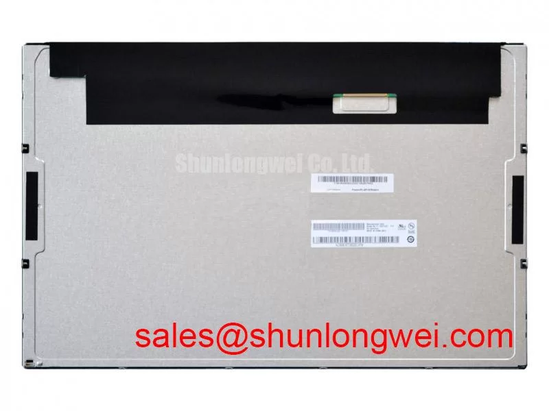
LM190E08-TLL3 LG Display Industrial Grade LCD HMI Panel
Begin incoming inspection by checking the LM190E08-TLL3 label against the service record, then examine the TFT-LCD module for cracked glass, frame distortion, connector damage, contamination, and visible pressure marks before applying power. The supplied product information identifies this unit as an LG Display Industrial Grade LCD/HMI Panel in a TFT-LCD Display Module format.
For maintenance teams, this identification is more useful than an assumed pinout or a guessed electrical rating. The available product record does not provide confirmed values for active-area dimensions, resolution, luminance, contrast ratio, interface voltage, connector pin assignment, backlight current, operating temperature, or optical surface treatment. Those values should be taken from the original panel documentation or the equipment manufacturer’s service data before a replacement is connected to a live control system.
| Item | Verified product information |
|---|---|
| Model | LM190E08-TLL3 |
| Manufacturer | LG Display |
| Product category | Industrial Grade LCD/HMI Panel |
| Construction category | TFT-LCD Display Module |
| Identification status | Model and category recorded in the supplied product information |
The panel may be evaluated for industrial HMI service, operator displays, monitoring terminals, and telematics consoles, including display assemblies used in heavy mining shovel or earthmoving equipment cabins. That application remains subject to system-level verification. Mechanical envelope, image interface, power sequencing, backlight control, vibration protection, enclosure sealing, and viewing conditions must match the original installation.
High-Nits Edge-Lit LED Rail Thermal Dissipation and Optical Preservation
Do not assume that the LM190E08-TLL3 has a particular luminance class, LED rail arrangement, PMMA light guide, anti-glare layer, or anti-reflection treatment unless the original LG Display documentation confirms it. These construction details are not included in the supplied factory parameter set. During incoming inspection, record the visible front-surface condition under controlled illumination and compare the replacement with the removed panel before installation.
When the equipment operates in direct sunlight, the practical inspection target is readable image contrast across the full screen rather than a nominal brightness claim. Test the panel with the intended host controller, cover the display area with uniform test images, and assess shadowing near the edges, corners, and mounting points. A contrast result such as greater than 500:1 at 50,000 lux must not be assigned to this model without a supporting optical datasheet or a controlled measurement report. The system integrator should verify the required sunlight readability from the original equipment specification.
Thermal review is also a system task. If the backlight assembly uses edge-mounted illumination, designers should examine whether nearby metal rails, brackets, seals, or cable retainers create localized heat accumulation. A heat spreader may be considered where it improves temperature distribution without transferring mechanical stress into the glass or obstructing the manufacturer’s mounting clearances. The rail material, contact area, insulation, and airflow path must be selected from the enclosure design rather than treated as fixed properties of this panel.
Backlight operating life is controlled by the actual LED current, driver temperature, PWM operation, enclosure temperature, and duty cycle. A claim such as 50,000 hours to 50 percent brightness, or an L70/B50 value, requires a manufacturer specification or a recognized test report. It should not be presented as an LM190E08-TLL3 factory rating from the information currently available. For field diagnosis, log initial brightness, supply conditions, driver status, and ambient temperature so later comparison is based on measured conditions.
Full-Screen Primary Color AOI Screening for Stuck Sub-Pixels and Uniformity
After the mechanical inspection, connect the panel only through a known-compatible controller and use full-screen red, green, blue, white, black, and neutral-gray images. Inspect the screen from the normal service viewing position, then repeat the check from modest off-axis angles. A fixed bright or dark point that remains in the same location across color changes may require pixel-level review, while a broad shadow or luminance gradient should be assessed as a possible uniformity or backlight issue. The observation alone does not establish a single failure cause.
A useful incoming QA record should include the screen condition before power-up, the image source, visible pixel locations, cable seating condition, and photographs taken at consistent exposure. A 45-degree flashlight inspection can help reveal surface scratches, pressure marks, frame interference, or localized optical shadows when the panel is displaying a dark image. It cannot, by itself, prove a COG driver fracture or isolate a particular internal defect. If a line defect changes when the cable is disturbed, stop flexing the assembly and compare the signal path with a known-good unit using the service documentation.
Do not apply a generic LVDS pinout to this model. The supplied data does not confirm the interface type, lane arrangement, voltage level, connector pitch, or cable assignment. If the equipment uses a differential display link, the integrator should verify the transmitter and receiver mapping, termination arrangement, polarity, timing, and cable construction against the original panel record. A nominal differential impedance target such as 100 ohms with a defined tolerance may be part of a system interface specification, but it is not an official LM190E08-TLL3 parameter unless documented by LG Display or the equipment maker.
In high-EMI factory environments, inspect the complete route from display controller to panel. Keep high-current switching conductors physically separated from the display cable where the machine layout permits, avoid unnecessary cable loops, and secure the harness so vibration does not load the connector. Skew tolerance, common-mode noise, and eye opening should be verified at the receiver with the actual cable and controller. A proposed skew budget, including values such as 50 ps, belongs to the system design record and should not be attributed to the display module without source documentation.
💡 Bench Tip: Use ESD protection, align the display cable squarely before locking the connector, and never insert or remove the FFC or LVDS cable while the panel or controller is energized.
Wide-Temperature Operational Margin and Sub-Zero Liquid Crystal Response
The supplied factory information does not confirm an operating range of −30 °C to +85 °C for the LM190E08-TLL3. It also does not provide a guaranteed gray-to-gray response time, sealant qualification, heater requirement, or thermal-cycle lifetime. These values must be verified from the original LG Display datasheet before the panel is approved for an outdoor cabin, mobile machine, or unconditioned control enclosure.
At low temperature, liquid-crystal response can become slower, which may appear as motion smear, delayed gray transitions, or an image that takes longer to stabilize after startup. That behavior should be evaluated with the complete display system at the actual temperature profile. Confirm whether the controller performs any startup delay, image initialization, or backlight sequencing, and measure the image response with a repeatable moving pattern rather than relying on visual impressions from a single cold start.
Temperature testing should begin with a baseline at room conditions. Record the panel image, backlight behavior, controller status, supply rails, and cable condition. Then expose the assembly to the intended thermal cycle while monitoring for condensation, frame stress, intermittent connectors, image retention, and changes in uniformity. The enclosure design should control moisture and thermal gradients; a heater strip may be considered only after the panel documentation and machine safety design establish that it is compatible.
Backlight reliability also depends on the constant-current driver used by the host equipment. Check for open-load, short-load, overvoltage, thermal, and current-limit responses at the driver output. A brightness decline curve or MTBF value cannot be assigned to the LM190E08-TLL3 without a source. The frequently quoted 50,000-hour figure to 50 percent brightness is therefore a verification item, not a confirmed specification in the supplied record. Engineers should request the relevant backlight data before using it in a maintenance forecast.
For practical compatibility work, compare the panel’s mechanical outline, active image area, connector location, and mounting features with the removed unit. The NL192108JC18-03ND can be reviewed as a separate same-size or same-resolution reference only after its own documentation is checked. Similar appearance does not establish electrical, optical, or mechanical interchangeability.
Suppressing Pixel Jitter and Horizontal White Lines Near Motor Drives
When a display is installed beside a high-power variable-frequency drive, begin diagnosis at the complete installation rather than replacing the panel immediately. Capture the fault timing, motor-drive operating state, cable position, display-controller status, and backlight behavior. Pixel jitter, horizontal white bands, or intermittent loss of image can involve signal integrity, grounding, power disturbance, connector movement, controller timing, or panel damage. The symptom does not identify one definitive cause.
Inspect the display cable for crushed sections, excessive bend, loose shielding, and routing alongside motor phase conductors. A shielded FFC or LVDS cable may be appropriate where supported by the original equipment design, but the shield termination must follow the system grounding architecture. A nominal “360-degree” shield bond should not be added blindly because chassis bonding, signal reference, protective earth, and high-frequency return paths vary between machines.
Common-mode ferrite suppression can be evaluated when conducted interference is confirmed, provided the selected part does not disturb the required differential signal waveform or power-up behavior. The correct location and impedance characteristics are system-dependent. Validate the change with an oscilloscope or suitable signal-integrity test method at the receiving end, comparing the waveform during quiet operation and during motor acceleration, braking, and regenerative events.
The display supply deserves the same attention as the data cable. Monitor supply ripple and transient behavior at the panel connector while the adjacent drive changes state. Confirm that the backlight driver does not enter an open-load or short-load protection mode, and check whether a brightness-control signal is being interrupted. The LM190E08-TLL3 record supplied here does not confirm PWM frequency, dimming method, LED current, or protection-output behavior. A proposed PWM operating window such as 200 Hz to 1 kHz must therefore be taken from the host controller and panel documentation, not treated as a model-specific factory value.
If a horizontal line remains fixed while the input image is changed, compare the panel with a known-good controller and inspect the connector under magnification. If the line follows the image source, investigate the controller and cable. If it remains with the panel under a verified compatible signal path, record the condition for technical assessment rather than applying pressure to the glass or bonded edge. For broader display interface and field-test guidance, engineers can consult The Ultimate Guide to Industrial TFT LCD Technology.
Before approving the LM190E08-TLL3 for a heavy mining shovel or earthmoving equipment telematics display, the responsible engineer should sign off the original interface documentation, mechanical fit, thermal range, sunlight readability, backlight drive, cable routing, and conducted-noise performance as separate acceptance items. The model identity and category are recorded; the remaining limits must come from the application records and the applicable LG Display documentation.