
Content last revised on September 28, 2026
Chassis Fastener Loading and Optical Mura Control
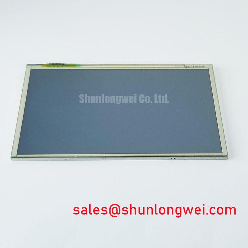
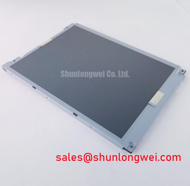
When a replacement panel is being fitted into an industrial console, inspect the chassis opening before tightening any fasteners. The bezel should sit evenly against its supporting surface, with no raised burrs, distorted brackets, trapped cable sections, or foreign material that could apply local pressure to the display. A panel that appears visually acceptable on the bench can develop bright zones, dark patches, or pressure-related mura after the chassis is tightened.
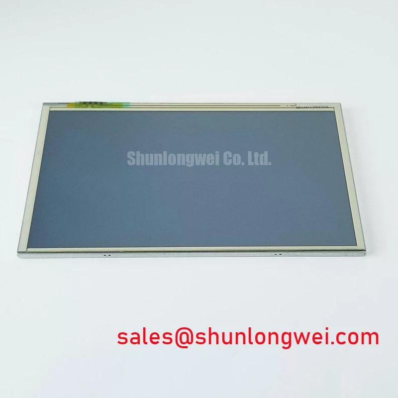
The supplied factory information for LMS700KF01-001 does not specify an M3 fastener torque, bezel tolerance, optical uniformity limit, or permissible compression load. These values must therefore be taken from the equipment manufacturer’s mechanical drawing or the original display assembly instructions. As a Design Consideration, tighten mounting points progressively in a cross-pattern so that the bezel load is distributed rather than concentrated at one corner. The correct torque remains a system assembly value, not an assumed specification for this Samsung display module.
Before final closure, power the panel using the approved equipment procedure and inspect a full-screen white image, mid-gray image, and dark image. Look for changes that appear only after the display is secured. If a defect changes when the chassis screws are loosened, record the mechanical condition and compare it with the known-good assembly. Do not treat one visual symptom as proof of a single internal failure; the same appearance can also be associated with cable seating, signal instability, backlight behavior, or panel damage.
Cold-start evaluation requires the same separation between verified data and engineering assumptions. The available product record does not publish a temperature range, gray-to-gray response time, heater requirement, or cold-start compensation profile for this model. If the display is considered for a heavy mining shovel or earthmoving equipment telematics cabin, the system engineer should confirm the panel’s environmental ratings from the original Samsung documentation and test image response at the actual enclosure temperature. A heater strip, if present in the equipment, should be controlled by the system designer according to the approved thermal and electrical design rather than added as an assumed panel requirement.
For a broader engineering reference on enclosure layout, display mounting, cable routing, and harsh-environment HMI integration, review Industrial Display & HMI Solutions. The purpose of that guidance is to support system evaluation; it does not add unpublished specifications to this model.
Edge Backlight Thermal Review and Optical Surface Preservation
Do not identify the backlight technology from the model number alone. The supplied factory record confirms the TFT LCD display module category, but it does not state whether the specific assembly uses an LED rail, another backlight arrangement, a defined optical guide material, a luminance value, a contrast ratio, or a rated brightness maintenance curve. The original panel documentation and the equipment service manual should control any replacement decision involving backlight wiring or driver compatibility.
During inspection, check the display frame and adjacent electronics for evidence of localized heat, discoloration, warped plastic, adhesive movement, or a connector that has darkened from thermal stress. These observations are useful troubleshooting evidence, but they do not by themselves establish the source of a failure. Measure the system’s backlight supply and control signals only with the approved test method and compare the result with the known-good unit or original equipment specification.
If the panel is installed behind a sealed industrial bezel, thermal evaluation should include the complete enclosure rather than the display alone. The designer should consider heat transfer through the rear support, clearance around the electronics, sunlight loading, airflow restrictions, and the temperature rise produced by nearby equipment. The panel manufacturer’s allowable operating and storage limits must be verified before qualification. No such limits are included in the supplied factory parameter set for LMS700KF01-001.
Direct sunlight can expose weaknesses that are not visible under workshop lighting. Evaluate the actual screen surface with the intended cover glass, window, anti-glare layer, and viewing angle in place. The available data does not provide a contrast-ratio threshold at a stated illumination level, nor does it confirm an anti-glare coating. Avoid publishing a numerical sunlight-performance claim unless it is supported by the applicable Samsung datasheet or an authorized optical test report.
Long-term static display operation also needs system-level consideration. Fixed status bars, alarm banners, and machine icons should be managed through the HMI software and operating procedure according to the panel technology and the equipment duty cycle. The supplied information does not provide an image-retention limit, burn-in qualification, LED half-life, or L70/B50 value for this model. These figures should be obtained from the original technical documentation rather than estimated from general LCD industry practice.
Backlight Control, Acoustic Noise, and Power Sequencing
When a field display presents a blank screen, faint image, white screen, unstable brightness, or residual image after shutdown, begin by separating the display module from the surrounding power and control circuits. Confirm that the host system is completing its normal startup sequence, then inspect the panel connector, backlight connection, ground path, and control wiring. A display symptom can result from an incorrect sequence, a missing enable signal, a supply disturbance, or a poor connection, so the diagnostic process should compare each stage with the original equipment documentation.
The available factory information does not publish the panel supply voltage, current consumption, power-on delay, power-off delay, display enable timing, PWM input range, dimming frequency, or backlight driver topology. It also does not confirm a CCFL inverter, constant-current LED driver, acoustic noise characteristic, or flicker-performance rating. The integrator should verify the required supply voltage and all timing requirements from the original panel documentation. Statements about a 200 Hz to 1 kHz operating window, a specific ignition voltage, or a defined dimming ratio would require a source that is not present in the supplied specification set.
For bench work, use a current-limited and correctly referenced test setup approved for the equipment. Observe the display during power-up and power-down rather than checking only the final image. If the image appears late, disappears during a supply transition, or remains visible after the system has been switched off, capture the relevant supply and control waveforms and compare them with the known-good path. This approach helps distinguish a panel issue from a host controller, backlight driver, grounding, or sequencing issue without assigning an unsupported single cause.
Acoustic noise should be checked near the complete assembly, not assumed to originate inside the LCD module. A buzzing sound can be associated with a driver, transformer, inductor, capacitor, mounting resonance, or enclosure vibration. The product record does not identify internal power components or provide a measured acoustic specification for LMS700KF01-001. If audible noise changes with brightness or refresh activity, document the operating condition and inspect the external driver and mounting structure under the equipment manufacturer’s service procedure.
⚠️ Field Alert: Disconnect power and follow the equipment discharge procedure before inserting or removing the display cable, because live connector handling can expose signal and power contacts to unintended electrical stress.
EMI Immunity, Cable Grounding, and Connector Retention
In equipment containing variable-frequency motor drives, contactors, long power runs, or high-current switching devices, inspect the display cable route before replacing the panel. Keep sensitive display wiring separated from noisy power conductors where the equipment layout permits, avoid sharp bends at the connector, and ensure that the cable is supported so vibration does not pull against the panel socket. The exact cable construction, LVDS assignment, shield termination, and connector locking method are not included in the supplied specification for this model and must be verified from the original assembly documentation.
Pixel jitter, intermittent horizontal bands, color instability, or a display that recovers after cabinet movement may indicate a signal-integrity or connection problem, but these symptoms do not prove a particular failure mechanism. Inspect the connector latch, contact alignment, cable seating, strain relief, and chassis bonding. Then compare the suspected path with a known-good signal route using the equipment manufacturer’s approved measurement method. If an oscilloscope is used, the probe arrangement and reference point should be selected to avoid changing the signal being measured.
Shielding is a system design matter. A continuous chassis reference can help control common-mode interference when it is compatible with the equipment grounding architecture, but the correct termination depends on the host design, cable construction, enclosure, and applicable safety requirements. Ferrite components may be evaluated as part of an EMI investigation when their impedance characteristics and placement are suitable for the affected frequency range. They should not be added as a universal cure or treated as a Samsung factory requirement for this display module.
For installations exposed to vibration, inspect the panel after the mechanical assembly has completed its environmental test sequence. Check for connector movement, bezel contact changes, cable abrasion, and new optical nonuniformity. The supplied data does not state a vibration rating, shock rating, connector retention force, or flex-cable bending life. Those values must be confirmed through the equipment qualification documents and the original display assembly requirements.
Before approving LMS700KF01-001 as a replacement, record the installed panel identity, mechanical fit, connector arrangement, supply requirements, image behavior, backlight control method, and environmental test results. Any unverified item should remain an open compatibility check until supported by the original documentation or a controlled engineering test.