Content last revised on September 27, 2026
Thermal Cycling, Gasket Contact and Display Response
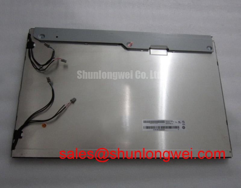
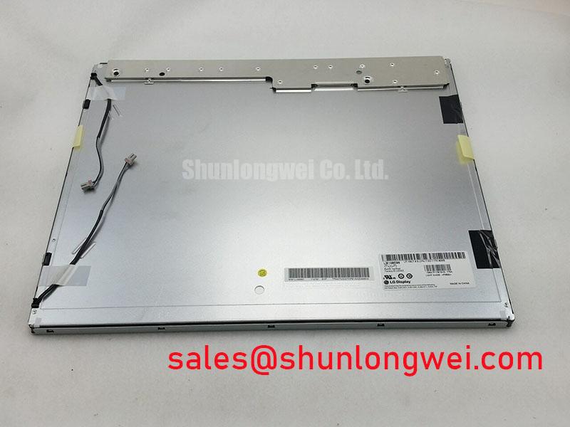
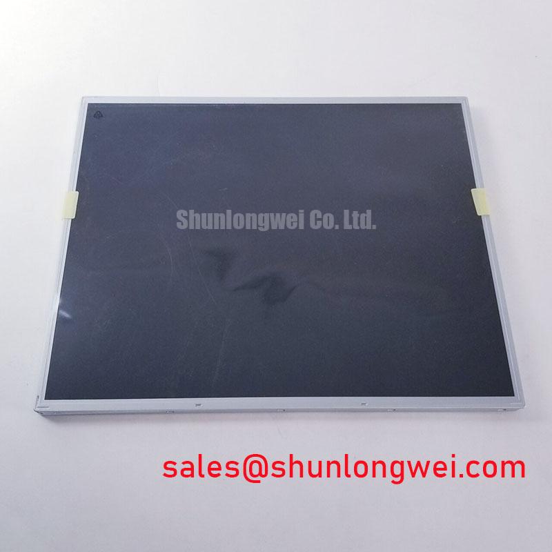
Inspect the LM190E08-TLGD bezel and connector area with power disconnected, then compare its label with the equipment service record before testing the display. The identified product is an LG Display TFT-LCD display module. Its model identity and module type are confirmed here; electrical limits, dimensions, interface assignments, backlight requirements and environmental ratings are not supplied in the available factory parameter record. A replacement assessment therefore needs the original panel documentation and the host equipment drawing, not a match based on model family or screen appearance alone.
During a cold-start inspection, let the panel and its host reach a stable, documented test condition before judging image response. Liquid-crystal response can slow as temperature falls, so a sluggish transition does not, by itself, identify a failed panel. Record whether the behavior changes as the assembly warms, using the same image sequence and camera settings for each comparison. The permitted operating-temperature range and any specified response-time limits for LM190E08-TLGD must be checked against its original documentation before a pass or fail decision. A proposed sub-zero test point or elevated-temperature soak should not be treated as a factory rating without that confirmation.
Inspect the enclosure gasket around the entire viewing aperture. Compression should be even, with no visible gap at a corner or evidence that the bezel is bearing directly on one narrow section of the glass. As a Design Consideration, uneven support can change the appearance of dark or mid-tone images under mechanical load; that observation is a reason to inspect the mounting, not proof of damage inside the module. Compare the image before and after releasing enclosure stress only under a safe, controlled service procedure. Keep the gasket’s sealing function in view as well: dust at the perimeter and moisture trapped behind the front window can complicate an optical assessment.
For equipment exposed to alternating warm and cold conditions, check for condensation on accessible surfaces before energizing the display. Allow the assembly to acclimate according to the equipment maker’s service procedure. Inspect perimeter bonding and external seals for visible separation without pressing on the active area. No adhesive chemistry, sealant lifetime or thermal-cycle rating is established by the supplied product information, so those observations cannot be converted into a predicted service life.
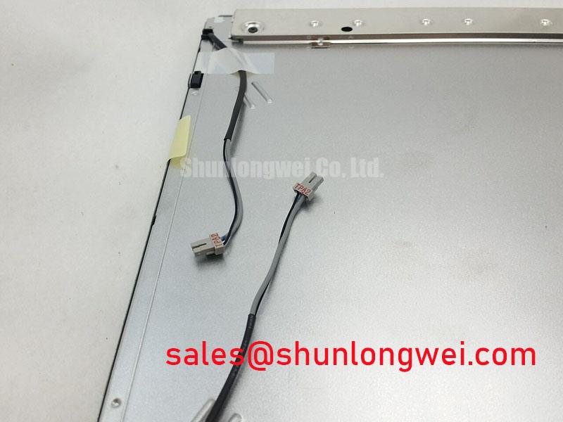
Cable routing matters during this inspection. Secure the flexible cable so enclosure vibration does not repeatedly work the connector, but leave enough movement to avoid a sharp fold at the termination. Confirm the latch is fully seated using the connector maker’s instructions. If an intermittent image appears only when the enclosure is closed, inspect cable strain and mating alignment before attributing it to temperature. Any differential-signal impedance or skew budget belongs to the documented host interface design; neither an interface type nor its numerical limits have been confirmed for this panel.
Full-Screen Primary Color Screening and Background Uniformity
Run full-screen red, green and blue patterns from a known-good source, followed by dark and mid-gray fields. This three-color bench sequence helps expose sub-pixels that do not follow the commanded image, while the neutral fields make broad brightness variation and pressure marks easier to see. Hold viewing position, brightness setting and ambient lighting steady, and photograph each pattern before changing the mounting. Record a defect’s location relative to the active area so the same spot can be checked after the panel is reinstalled.
A colored point that persists through the patterns calls for closer inspection; a line that changes when the cable is reseated calls for an interface-path check. Neither observation proves a single cause. Inspect the connector and accessible cable for contamination, incomplete insertion or strain, then compare the source waveform and image with a known-good path where the service setup permits. Do not assume a line is a driver micro-fracture from its appearance alone. Pixel acceptance criteria, if needed for a procurement decision, should come from the applicable factory specification or the equipment’s agreed inspection standard rather than an invented defect allowance.
For a dim or dark region, a low-angle light can help distinguish an image that is present but poorly illuminated from an area where the commanded image is absent. Use it as a comparative observation, not a definitive backlight diagnosis. Inspect through the normal viewing surface without pressing on it. If the pattern is visible only under external light, the next checks concern the documented backlight supply and control path. If the pattern itself is missing, continue with the video source, cable and connector. Avoid assigning a connector pin or probing a presumed supply rail until the original pinout is in hand.
A heavy mining shovel or earthmoving-equipment telematics display is a possible compatibility evaluation, not a stated design application for LM190E08-TLGD. For that evaluation, compare the original assembly’s aperture, mounting support, connector orientation, image requirements and environmental limits with the replacement documentation. NL192108JC18-03ND can be included in a documented comparison, but its fit, resolution and electrical compatibility should be verified independently rather than inferred from its listing.
Backlight Driver Identification and Cold-Start Debugging
Identify the installed backlight and its driver from the original panel documentation and the equipment wiring diagram before applying power. The available product parameters do not establish a lamp technology, channel count, striking voltage, driver current or dimming method for LM190E08-TLGD. Applying a voltage borrowed from another display would turn a diagnostic check into an uncontrolled test. Trace the host supply, enable signal and brightness-control path as documented, then measure them at accessible points using the equipment maker’s safety procedure.
If illumination fails only after a cold soak, log the panel temperature condition, supply behavior, enable state and visible image behavior during the same start attempt. A brief flash, delayed illumination or audible noise is an observation to correlate with driver and power measurements; it is not proof of a particular lamp fault. Compare against a known-good assembly under matching conditions when one is available. Keep high-voltage sections enclosed during normal operation, and use appropriately rated instruments for any authorized service measurement.
Video timing requires the same discipline. Confirm the specified interface and transmitter configuration before assessing clock quality, data timing or signal integrity. If the picture breaks up while illumination remains steady, check the documented signal path and connector seating, then compare waveforms at defined test points. Clock-jitter margins and hold-time requirements cannot be assigned to this model from the provided information. They must be taken from the original panel specification and validated with the host controller across the equipment’s intended temperature range.
LQ201U1LW31 is another display product that may be reviewed when mapping a system’s display options; its driver or backlight arrangement should not be transferred to this module. For LM190E08-TLGD, verify the required supply voltage, startup sequence and backlight connection from its own documentation before selecting or testing associated electronics.
Edge Mounting, Heat Flow and Optical Uniformity in Continuous Operation
After the display has run long enough to reach a stable condition permitted by its documentation, compare bright and dark test fields with the initial inspection images. Look for changes near the edges, but first check whether the front frame, gasket or cable has shifted as the enclosure warmed. As a Design Consideration, a heat spreader or support rail can affect both heat flow and mechanical loading. Any added rail therefore needs a clearance and mounting review by the equipment designer; it should not press on the module to correct an unverified internal hot spot.
Do not assign yellowing to a particular diffuser material, or promise a backlight longevity target, without the module’s construction and test data. A change in color or uniformity can also involve the source image, brightness control, viewing surface or enclosure window. Repeat the same pattern under the same lighting, inspect accessible surfaces, and compare the display with the enclosure open and closed only where the service procedure allows. This separates an observed optical change from a diagnosis that the available evidence cannot support.
Pay close attention to the cable path during reassembly. A flexible tail should not be trapped beneath a support or drawn tight when the front frame is secured. Tighten the enclosure hardware according to its documented procedure, checking that the gasket remains seated around the aperture and that the visible image does not change as the frame settles. If vibration is part of the host equipment’s duty, evaluate connector retention and strain relief against that equipment’s requirements; the supplied panel information does not establish a vibration rating.
Maintenance Note: Disconnect power before reseating the display cable, and inspect the enclosure airflow path and perimeter gasket during scheduled service. For a recurring fault, preserve the color-pattern images, temperature condition, connector observations and host measurements in the service record. The diagnostic framework in Industrial Display & HMI Solutions can support that investigation, while the final acceptance decision remains tied to the original LM190E08-TLGD specifications and the host equipment’s requirements.