

Content last revised on September 10, 2026
Thermal Expansion Clearance Sizing across Heavy Industrial Metal Enclosure Cutouts
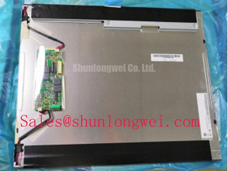
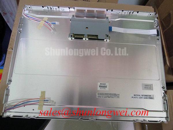
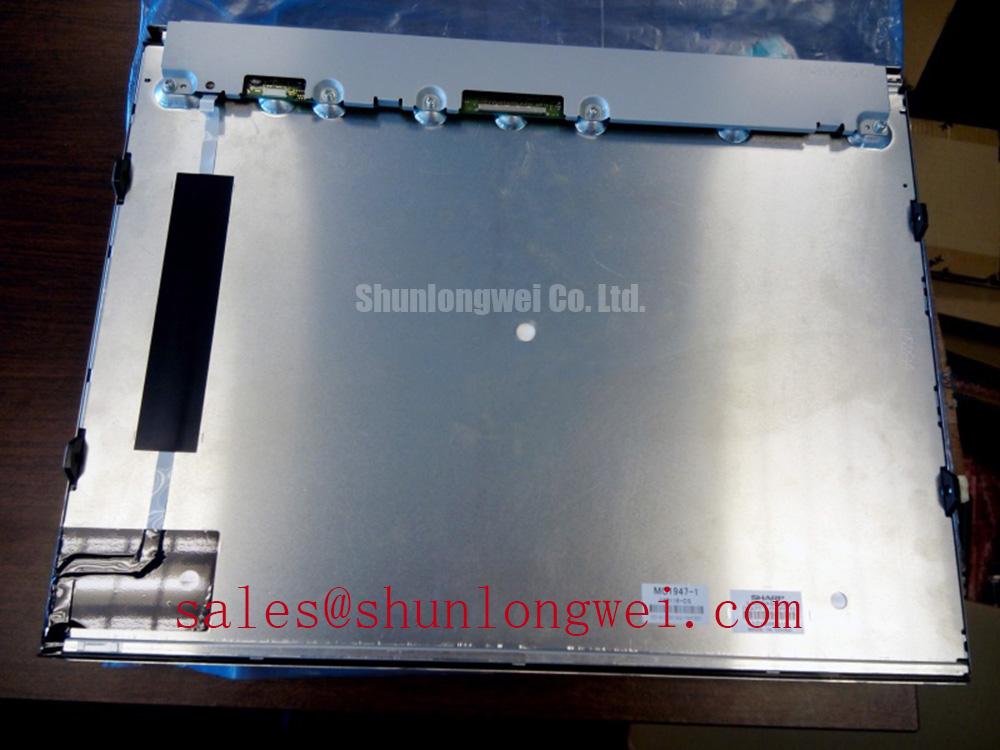
When the LQ201U1LW31 is installed behind a metal control-panel cutout, begin with a mechanical comparison rather than tightening the fasteners immediately. Measure the opening, bezel contact surfaces, screw-hole locations, connector clearance, and the position of any rear support bracket. Compare these measurements with the original panel drawing or the display removed from the equipment. A panel that fits into the opening can still be unsuitable if the bezel is forced against the enclosure or if the rear cable exits at an unsuitable angle.
The supplied factory data does not provide the outer bezel dimensions, active display area, hole spacing, or approved mounting torque for this model. Those values must be confirmed from the original Sharp documentation or the equipment manufacturer’s mechanical drawing. A general engineering recommendation is to let the enclosure, gasket, and display bezel establish their own contact surfaces without twisting the glass assembly. Fasteners should be tightened in a cross pattern only after the panel is seated evenly. The final torque remains system determined unless a documented Sharp or equipment specification states otherwise.
Localized pressure can produce uneven optical appearance, intermittent touch or display behavior, or mechanical stress that becomes more apparent after thermal cycling. These symptoms should not be assigned to a single cause without inspection. Check whether the enclosure is distorted, whether a gasket is displaced, and whether the panel is being loaded by a rear cable or nearby bracket. If the original assembly used a floating mount, retaining that mechanical principle is generally preferable to converting it into a rigid clamp without validation.
Optical bonding, sealing, and anti-condensation measures also require evidence from the original assembly. The available information does not confirm that the LQ201U1LW31 includes factory optical bonding, a specific liquid-crystal seal construction, or a defined ingress protection rating. For a harsh marine radar or navigation bridge console, designers should evaluate enclosure sealing, salt-laden airflow, service access, and condensation control at the complete equipment level rather than attributing environmental protection to the LCD module alone.
💡 Bench Tip: Use ESD protection, keep the flexible cable parallel to the connector, and engage the locking mechanism evenly before applying power or performing a full-screen test.
Backlight Drive, Dimming, and Flicker Evaluation
Backlight compatibility is a critical checkpoint during replacement work. The available factory parameter set does not identify the LQ201U1LW31 backlight type, LED current, LED voltage, dimming method, brightness range, or connector pinout. The system integrator should verify the required supply and backlight drive conditions from the original panel documentation. Do not connect an assumed LED driver or reuse a CCFL inverter simply because the connector appears mechanically similar.
For an LED-backlit system, the host electronics normally need to provide a compatible constant-current drive path or a validated external driver. The permitted current range, enable logic, fault behavior, and PWM input characteristics are system-specific unless they are stated in the Sharp datasheet. If the replacement assembly uses a separate backlight driver, confirm the driver’s startup behavior with the display controller so that the panel does not receive an invalid sequence during power-on or shutdown.
Claims involving 1000:1 PWM dimming, a particular PWM frequency, acoustic noise, flicker performance, or a defined half-life cannot be treated as specifications for this model without a supporting factory source. These are evaluation criteria, not confirmed LQ201U1LW31 ratings in the supplied data. During bench testing, inspect brightness transitions with a photodetector or suitable optical instrument when the application is sensitive to flicker. Check the backlight enable waveform and supply ramp with an oscilloscope while the display is connected to the intended controller.
For high-contrast control screens, inspect the panel at low, medium, and maximum commanded brightness. Look for brightness steps, unstable startup, visible modulation, and uneven luminance across the active area. A visual check should be performed with full white, full black, red, green, blue, and mid-gray images. This provides a practical way to separate backlight irregularity from image-data problems without inventing a diagnostic voltage threshold.
The host system should also be checked for a clean power-down sequence. Residual image, a bright flash, or a delayed black screen may involve panel control timing, backlight enable timing, stored charge, or the controller board. Verify the complete sequence against a known-good assembly and the original documentation. A replacement display should not be judged by a single symptom in isolation.
Temperature Evaluation and Sub-Zero Liquid Crystal Response
The supplied factory information does not confirm an operating temperature range, storage temperature range, gray-to-gray response time, contrast ratio, viewing angle, or low-temperature optical behavior for the Sharp LQ201U1LW31. These values must be obtained from the applicable Sharp specification sheet before the module is approved for an outdoor or thermally exposed installation. A marine bridge console may experience rapid changes in enclosure temperature, direct solar loading, chilled air, and condensation, so the display should be assessed within the complete enclosure and power system.
At low temperature, liquid-crystal response can change and may produce visible transition lag or gray-level nonuniformity. That physical possibility does not establish a numerical limit for this model. A practical engineering recommendation is to perform a controlled cold-start and warm-up evaluation using the actual controller, backlight drive, and image content. Record whether text remains readable, whether moving symbols show trailing, and whether the image recovers as the panel reaches the intended operating condition.
At elevated temperature, inspect the bezel, cable routing, rear support, and ventilation path together. Do not place a heat source directly against the panel or assume that an enclosure fan solves every thermal problem. The equipment designer should measure the temperature at relevant locations during representative operation and compare the results with the approved Sharp limits. Any thermal derating or enclosure change must be validated at system level.
Wide-view optical behavior also deserves a controlled inspection. The supplied data does not identify whether this particular panel uses an IPS, MVA, or another LCD optical arrangement, so those characteristics should not be inferred from the model number. Evaluate readability from the operator’s actual viewing positions, including vertical movement and side viewing. Check color shift, black-level change, and gray-scale visibility using consistent test images rather than relying on a single viewing angle.
For field replacement planning, document the complete display identity before removing the original unit. Record the cable orientation, controller-board markings, mechanical supports, backlight connection, and any configuration stored in the host system. If the original supply voltage or timing information is unavailable, the system integrator should obtain the panel documentation before energizing the replacement. A same-size display from another family, such as LM190E08-TLG6, should be treated as a separate compatibility investigation rather than an automatic substitute.
Radiated Emissions Evaluation and Backplate Grounding in Variable-Frequency Drive Environments
Install the LQ201U1LW31 with the same cable routing used by the original equipment whenever possible, then inspect the video path while nearby switching equipment operates under representative load. Pixel jitter, horizontal noise bands, intermittent image loss, and brightness disturbance can arise from several interacting conditions, including cable routing, connector contact, reference-potential differences, power-supply noise, shielding, or controller timing. A single observed symptom should not be assigned to one source without comparing the signal path and operating conditions.
The supplied factory data does not state a CISPR classification, EMC approval, shield termination method, LVDS pinout, differential impedance, or allowable pair skew for this display module. The LQ201U1LW31 should therefore not be described as independently certified to a complete equipment EMC standard. Compliance is assessed on the assembled product, including the host controller, cable, enclosure, power supply, and grounding arrangement.
As a design consideration, keep high-current motor-drive conductors physically separated from display and data cables, avoid unnecessary cable loops, and preserve the original differential-pair routing. If the display uses an LVDS or other differential interface, the integrator should verify the connector assignment and transmission requirements from the original documentation. Do not rely on a visually matching cable because pin order and shield arrangement may differ between panel families.
Grounding should be evaluated as a complete current-return path. The enclosure, display backplate, cable shield, controller reference, and protective earth may not share the same electrical function. A low-impedance shield connection can help reduce common-mode coupling, but the final arrangement depends on the equipment topology and safety design. Ferrite components may be considered only after measuring the disturbance and confirming that their impedance characteristics are appropriate for the affected frequency range.
For structured troubleshooting, first compare the display with the drive disabled, then repeat the test while the variable-frequency drive changes speed and load. Observe both the image and the display supply with appropriate measurement equipment. Inspect connector seating, cable strain, shield continuity, and enclosure bonding before changing firmware or replacing the panel. The The Ultimate Guide to Industrial TFT LCD Technology provides broader technical context for TFT panel interfaces, selection checks, and common integration misunderstandings.
For a harsh marine radar and navigation bridge console, the final acceptance test should combine optical inspection, power-sequence verification, mechanical fit assessment, cable retention, thermal observation, and electromagnetic testing in the completed enclosure. The LQ201U1LW31 remains a Sharp TFT LCD display module identified by the supplied factory information as an industrial-grade LCD/HMI panel; all unlisted electrical, optical, dimensional, environmental, and interface values require confirmation from the applicable original documentation.