Content last revised on October 4, 2026
Incoming Benchtop Inspection: Connector Condition and Image Defects
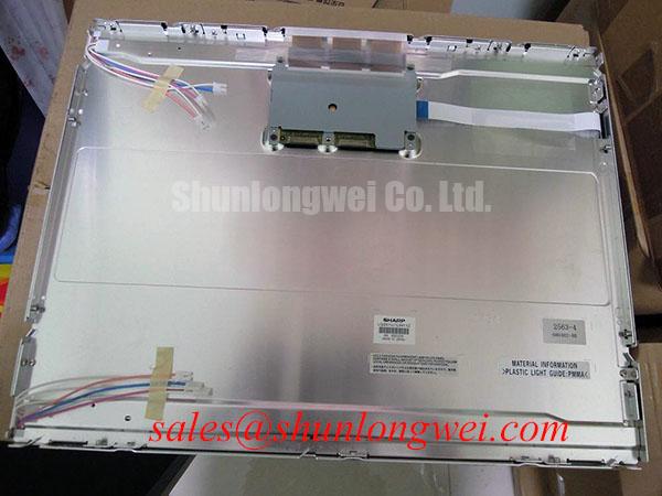
Inspect the connector and display surface of the Sharp LQ201U1LW11Z under angled light before applying power, recording any contact damage, scratches or visible pressure marks. The supplied product identification classifies it as an industrial grade TFT-LCD display module (Official Factory Specification). Electrical, optical and mechanical values not provided with that identification need confirmation against the original panel documentation before the module is connected to a test fixture or assessed for equipment replacement.
Begin with the module unpowered. Inspect the connector housing, mating contacts and cable seating area, then photograph any irregularity before handling the cable. Check that the fixture supports the panel without loading the visible display area. A screen that looks intact from the front can still be difficult to evaluate if a cable sits unevenly or the test fixture presses on one edge.
Once the system integrator has confirmed the supply voltage, pin assignment and power sequence from the original panel documentation, run a controlled primary-color test: display full red, full green and full blue fields in succession. Record persistent dark or bright pixels by location and note whether any line defect remains fixed as the image changes. Follow with white, gray and black fields to expose nonuniform illumination and contrast defects that saturated colors can conceal. Use the applicable acceptance criteria from the equipment owner or original documentation rather than assuming a universal pixel-defect allowance.
A flashlight held at an angle can help distinguish a missing image from an image that is present but poorly illuminated. If faint graphics remain visible when the display appears dark, investigate the installed illumination circuit and its connections; if a line defect persists across test patterns, compare the incoming signal and cable path with a known-good setup. Neither observation alone establishes a particular driver-bond or backlight fault. The internal bonding construction of LQ201U1LW11Z is not established by the supplied product identification, so an inspection report should describe the observed defect rather than assign it to a presumed COG, TAB or ACF structure.
💡 Bench Tip: Remove power and use ESD precautions before reseating the display cable, then confirm that it enters the connector squarely and locks evenly.
For replacement screening, compare the actual outline, active area, mounting points, connector position and electrical interface rather than relying on a similar-looking front view. The LM190E08-TLG6 is another panel to assess on those criteria, not a verified drop-in substitute for the LQ201U1LW11Z.
Temperature Margin and Power Sequencing in the Installed Equipment
At low temperature, liquid-crystal response can slow, making transitions between gray levels appear less distinct in moving text or graphics. That is a general display design consideration, not a verified operating-temperature or gray-to-gray response rating for this Sharp module. Before qualifying the LQ201U1LW11Z for a cold or hot enclosure, obtain its documented operating and storage limits and evaluate the complete display assembly at the temperatures the equipment will encounter.
During a temperature test, keep the same image pattern, measurement location and viewing geometry at each checkpoint. Compare gray transitions and readability with the equipment’s acceptance requirements. Inspect the perimeter and connector region after thermal cycling for changes that were not visible at incoming inspection, without assuming a particular sealant formulation or internal failure mechanism. Record the panel temperature and the conditions under which each image was captured; otherwise, a change in brightness can be mistaken for a change in pixel response.
Power sequencing deserves a separate check. The system integrator should verify the required supply voltage, signal timing and illumination-control sequence from the original panel documentation. On the bench, observe what the host and display supplies do at startup and shutdown, then compare that behavior with the documented requirements. If the installed system dims its display, assess visible flicker and brightness stability across the dimming range; a PWM frequency or duty-cycle requirement must come from the relevant display and driver documentation, not from the model name alone.
The LMS700KF01-001 is a separate display product that may be reviewed when comparing display-system requirements. Its supply or illumination arrangement should not be treated as a specification for the LQ201U1LW11Z. For equipment such as a hazardous-area petrochemical operator station, panel temperature performance is only one part of the assessment: the enclosure, installation and complete equipment must be evaluated against their applicable requirements. The Industrial Display & HMI Solutions reference provides broader integration considerations, while the original panel and equipment documents remain the basis for acceptance limits.
Dark-Field Uniformity and Bezel Pressure
Display a uniform dark-gray field before and after fitting the panel into its bezel. Inspect it from the intended operator position under consistent room lighting, then repeat with a white field. Photograph any newly visible bright patch, dark patch or color shift with the test image and exposure settings recorded. This comparison can reveal assembly-induced mura without presuming that a particular light-guide material or internal stack is present in the LQ201U1LW11Z.
Check whether bezel contact is even and whether the mounting arrangement bears on designated support features rather than the viewing area. If an optical defect appears only after installation, release the fixture in a controlled manner and repeat the image test. A change after release makes mechanical loading worth investigating, but it does not by itself identify the affected internal layer. Mounting torque and chassis tolerances must be taken from the applicable mechanical drawings and equipment assembly procedure; no model-specific limit is established by the supplied specification.
Separate mounting effects from signal effects during this inspection. A fixed patch confined to an area of a uniform field calls for a different investigation from intermittent image breakup that follows cable movement or changes with the host. If the host uses a differential display link, verify its connector assignment and signal requirements before probing. Controlled differential routing and timing margin are design considerations for preserving image integrity, but no interface type, trace-impedance target, clock-jitter limit or data-hold value is confirmed here as an official LQ201U1LW11Z rating.
Illumination also affects dark-field interpretation. Measure brightness at repeatable positions only after the installed illumination system has reached a stable operating condition, and compare the pattern with the equipment’s specified acceptance method. A locally warm or bright region warrants inspection of the enclosure’s airflow, nearby heat sources and mounting pressure; it should not be attributed to an assumed backlight construction without supporting documentation.
Polarizer and Surface Inspection Under Operator-Station Lighting
Inspect the powered panel at the angles an operator will actually use, not just directly in front of the screen. Present a grayscale ramp and text with fine strokes, then move through the intended viewing positions while noting contrast loss, reflected light and any apparent gray-level reversal. Those observations support an equipment-level readability assessment. They do not establish whether the LQ201U1LW11Z uses a particular liquid-crystal mode or has a specified symmetric viewing cone.
With the display unpowered, examine the surface under grazing light for scratches, uneven sheen and edge lifting. Repeat the inspection powered with a dark image and the overhead lighting used at the workstation. Reflections can obscure text even when the image itself is stable, so record the light-source position alongside photographs. Do not assign an anti-glare etch, anti-reflection coating or polarizer durability rating to this model without its optical specification.
If a touch overlay is part of the operator station, evaluate it as a separate assembly. Confirm its sensing technology, controller, cover construction and interface from the equipment records before testing glove use or wet-touch behavior. Likewise, image disturbance that occurs near running servo equipment calls for measurements at the installed power and signal paths, cable routing and enclosure bonds. The panel’s product category alone does not establish an equipment-level EMC rating.
Finish the inspection with a traceable record: module identification, fixture and host used, documented electrical settings, image patterns, lighting conditions, photographs and unresolved discrepancies. For a petrochemical operator station, the equipment owner should compare that record with the original display requirements and the station’s hazardous-area documentation before approving an installation.