Content last revised on September 10, 2026
Suppressing Localized Thermal Gradients to Prevent Chronic Optical Yellowing and Color Shift
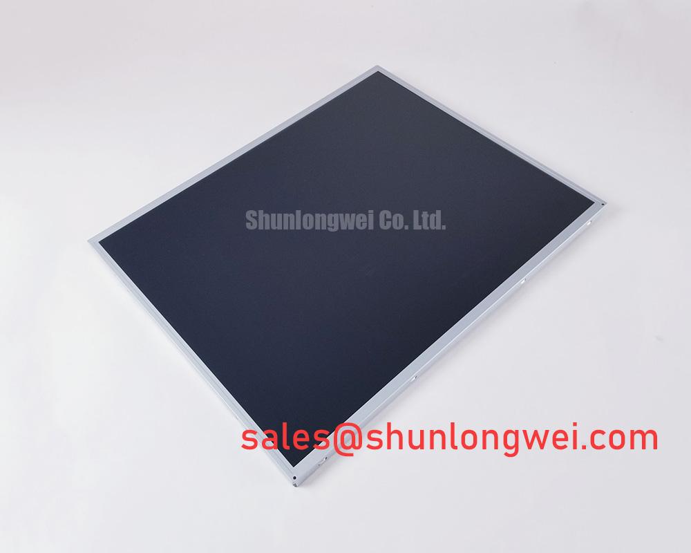
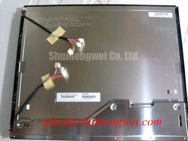
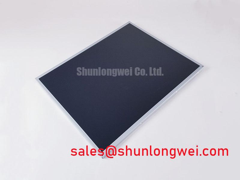
Begin the replacement check by isolating system power, inspecting the panel connector and cable, and comparing the installed nameplate with LTM190ET01. This unit is identified as a Toshiba / Samsung Industrial Grade LCD/HMI Panel with a TFT LCD display module construction; detailed factory specification data is not included here. Before installation in an industrial display assembly, technicians should confirm the original panel documentation, connector assignment, display timing, mechanical envelope, and backlight arrangement.
| Item | Verified information |
|---|---|
| Model | LTM190ET01 |
| Manufacturer | Toshiba / Samsung |
| Product category | Industrial Grade LCD/HMI Panel |
| Display construction | TFT LCD Display Module |
| Specification status | Product identity supplied; detailed factory data not included |
The information above is the confirmed product identity supplied for this product page. Electrical values that are not included in the available factory data should be taken from the original panel documentation rather than inferred from a similar display. This is especially important when a service replacement is being considered for a heavy mining shovel, earthmoving machine telematics display, operator cabin monitor, or another vibration exposed HMI enclosure.
When a failed display is removed from an industrial enclosure, first inspect the rear surface, edge regions, mounting frame, and nearby power components for uneven heat exposure. A dark corner, gradual color change, or persistent optical tint can involve the display module, its backlight system, heat transfer through the enclosure, or the upstream display electronics. These observations should be recorded before the replacement is powered, because a new panel can show similar symptoms if the original thermal condition remains in the equipment.
LTM190ET01 is identified here as a TFT LCD Display Module, but the supplied factory data does not confirm a specific optical plate material, LED lifetime rating, L70 or B50 value, or internal heat spreading construction. Those values must not be assigned to this model without the applicable manufacturer document. As a Design Consideration, the system integrator can evaluate whether heat from adjacent converters, backlight electronics, sealed cabinet surfaces, or direct solar loading is creating an uneven temperature profile across the panel. The useful method is to compare several points across the installed display during normal operation and during the highest expected enclosure load.
Any added aluminum rail, bracket, or thermal interface should be treated as a system modification rather than a factory feature of this display. It should not press against the active area or distort the mounting frame. Designers should preserve the panel’s intended mechanical support, avoid concentrated edge loading, and verify the result under the actual enclosure temperature range. If a backlight driver is separate from the panel, its output, enable signal, and fault behavior should be checked independently rather than treating a dark image as proof of LCD failure.
High EMI equipment can also produce image instability that resembles optical damage. The display cable should follow a controlled route away from switching power loops and high current conductors where practical. Differential routing, shielding, termination, and connector retention remain system responsibilities. A differential impedance target or skew budget should only be used when it is specified by the panel interface documentation and validated against the transmitter, cable, and receiver combination.
For engineers comparing display options within a similar industrial maintenance program, NL192108JC18-03ND can be reviewed as a separate reference product. It should not be treated as an automatic substitute for LTM190ET01. Interface assignment, mechanical fit, optical behavior, timing, and backlight requirements must be matched from the relevant documentation before any substitution decision.
VESA Versus JEIDA Data Mapping Alignment and Even or Odd Channel Signal Integrity
A replacement panel should be connected only after the system integrator has identified the original interface standard and pin assignment. The available product identity confirms the display module category, but it does not provide a verified logic supply voltage, LVDS channel map, VESA or JEIDA selection, pixel clock range, power sequencing specification, or connector pinout. The system integrator should verify the required supply voltage from the original panel documentation.
When a screen powers but shows split images, incorrect colors, unstable bands, or an apparently reversed pixel arrangement, the investigation should begin with the known good signal path. Record the transmitter configuration, cable orientation, connector keying, channel order, data mapping, clock polarity, and display enable behavior. An oscilloscope can be used to compare the clock and differential data activity at the source and panel connector, while the service team checks whether the observed behavior changes when the cable is gently secured without applying force to the panel.
VESA and JEIDA mapping are not interchangeable assumptions. A compatible electrical connector does not prove compatible bit mapping. Even and odd data channels must be checked against the panel documentation, and the timing controller configuration should remain unchanged until the physical connection has been verified. If the machine uses a custom carrier board, its pullups, level translation, enable logic, and startup sequence should also be reviewed.
Cold equipment environments deserve a separate timing and optical check. Liquid crystal response can change with temperature, and a slower visual response may be reported as trailing, ghosting, or delayed screen updates. The supplied factory information does not confirm the operating temperature range, response time, heater provision, or cold start behavior for this specific panel. A heater strip or cabinet warming method should therefore be evaluated only as part of the complete equipment design, with temperature limits taken from the original display documentation.
⚠️ Field Alert: Disconnect system power and allow stored energy to discharge before inserting or removing the display cable, because live connector handling can expose signal and supply contacts to electrical stress.
A related display solution such as LQ201U1LW31 may be relevant when reviewing a broader panel and driver topology, but its specifications do not define the interface requirements of LTM190ET01. For a replacement assessment, engineers should compare the complete cable and controller arrangement rather than selecting by screen size or connector appearance alone.
Thermal Expansion Clearance Across Heavy Industrial Metal Enclosure Cutouts
Remove the original panel without levering against the glass or twisting the frame. Inspect the enclosure cutout, mounting points, gasket contact, bezel opening, and cable exit path before installing the replacement. A metal cabin enclosure can transfer vibration and mechanical stress directly into the display frame. If the opening is misaligned, tightening the fasteners may introduce pressure that appears later as nonuniform brightness, lines, or intermittent operation.
The confirmed product information does not include the external dimensions, active area, mounting hole pattern, bezel envelope, fastener specification, or allowable panel deflection for LTM190ET01. These dimensions must be checked against the original factory drawing or the removed unit. M3 torque values, gasket compression, spacer thickness, and clearance around the bezel are Design Considerations unless explicitly provided by the manufacturer. The correct installation condition is the one that secures the module without compressing the display area or forcing the frame into an uneven enclosure surface.
For field replacement work on telematics displays, measure the enclosure before ordering or fitting a panel. Confirm the visible opening, rear clearance, connector direction, cable bend path, and access for the controller board. A mechanically similar display can still fail the installation review if the cable exits into a bracket, the bezel overlaps the active area, or the mounting points pull the module out of plane.
Direct sunlight and reflective cabin conditions can make a healthy display appear weak or washed out. The available factory data does not confirm a contrast ratio at a specified illumination level, anti glare coating, viewing angle, or sunlight readability rating for this model. These characteristics should be verified from the original optical specification when the panel is intended for an exposed operator cabin. Do not describe a particular contrast performance or coating as an LTM190ET01 factory feature without supporting documentation.
For broader enclosure and service planning, the Industrial Display & HMI Solutions reference provides useful system level context. The installation team should still validate the actual cutout and display drawings for the equipment being repaired.
Separating Backlight Drive Noise from Display Data Faults
When the field symptom is a black screen, begin by checking whether the panel is receiving its specified supply and whether the host system is producing a valid display signal. A visible image under a controlled light source can suggest that the LCD data path is active while the backlight path requires separate investigation, but this observation is not a definitive diagnosis. Check the original backlight wiring, driver enable state, fault output, connector contact, and cable insulation according to the equipment schematic.
The supplied factory information does not verify whether this specific LTM190ET01 assembly uses a particular CCFL arrangement, LED configuration, ignition voltage, PWM dimming ratio, acoustic behavior, or rated service lifetime. Engineers should not apply generic backlight values to this model. If the installed equipment uses an external driver, the driver documentation governs its output and protection requirements. If the display assembly includes an integrated driver, the panel documentation governs the permitted control signals.
Audible noise from a display cabinet can originate from a driver, transformer, inductor, mounting surface, or another power component. To separate acoustic symptoms from image faults, technicians should compare the sound with backlight enable active and inactive, inspect the driver waveform with suitable measurement equipment, and verify that the display cable is not routed through a high field region. The external reference on impact ionization and avalanche multiplication explains a power semiconductor mechanism, but it is not a specification or lifetime guarantee for this LCD module.
Clock and data integrity should be reviewed at the transmitter and receiver side of the display link. Observe whether the fault follows the cable, remains with the panel, or changes when the host controller is replaced with a known good unit. This approach helps separate connector contact problems, power sequencing issues, mapping errors, and panel faults without assigning a single cause prematurely. Any electromagnetic compatibility evaluation belongs to the complete display assembly and equipment; the LCD module itself should not be represented as independently certified for an entire machine standard.
Before final fastening, verify the connector latch, cable strain relief, enclosure bonding, and startup behavior during repeated cold and warm power cycles. Keep the replacement record tied to the exact LTM190ET01 identification and the original equipment documentation so future technicians can distinguish panel behavior from controller or backlight driver behavior.