



Content last revised on September 10, 2026
AUO G190EG02 V0 Integration and Inspection
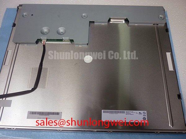
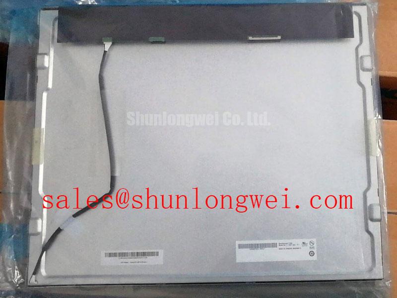
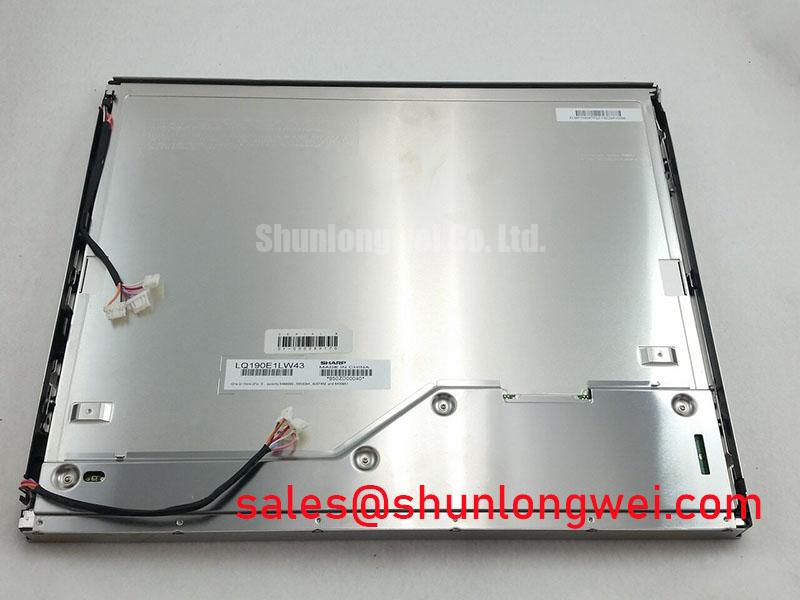
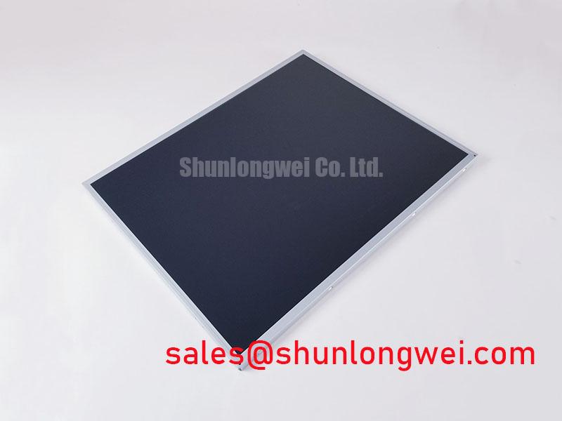
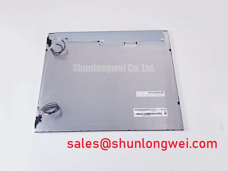
Before fitting the G190EG02 V0, inspect the TFT LCD display module’s front surface, perimeter frame, connector area, and rear enclosure under angled light, then compare the installed unit’s physical interface and label information with the original equipment documentation. This AUO industrial-grade LCD/HMI panel is identified as a TFT-LCD Display Module. Electrical supply requirements, signal standard, pin assignment, optical values, environmental limits, and mechanical drawings must be confirmed from the original panel documentation before replacement or new-system integration.
| Model | G190EG02 V0 |
| Manufacturer | AUO |
| Product Category | Industrial Grade LCD/HMI Panel |
| Module Format | TFT-LCD Display Module |
| Specification Status | Detailed specifications require verification against original AUO documentation |
Flush-Mount Open-Frame Bezel Integration & Perimeter Gasket Shock Isolation
A flush-mounted display should be checked as a mechanical assembly rather than treated as a panel that can simply be clamped into a cutout. Begin by placing the G190EG02 V0 into the intended bezel without tightening hardware. Confirm that the metal frame rests evenly, that the viewing area is not contacted by the bezel, and that a perimeter gasket does not create isolated pressure points. Localized compression can appear later as uneven dark-field appearance, edge brightness variation, or image disturbance that changes when the enclosure is flexed.
Design Consideration: fastening locations should be tightened progressively in a cross-pattern sequence so that bezel load is distributed around the frame. The correct fastener type, tightening torque, gasket thickness, compression allowance, and enclosure opening tolerance are system-defined items. They should be validated against the mechanical drawing for the original display and the equipment chassis, rather than transferred from another panel family.
Where a telematics terminal is exposed to vehicle vibration, the integration team should evaluate whether the enclosure support structure carries shock loads around the display frame instead of through the active viewing region. A compliant perimeter gasket can help decouple enclosure distortion, but its material, geometry, and retention method need review against the application’s mechanical environment. Do not infer backlight lifetime, retained luminance, or thermal-cycle capability from the G190EG02 V0 model name alone. Those values require the applicable AUO documentation and the operating current profile of the host backlight driver.
⚠️ Field Alert: Tightening a bezel before verifying a uniform frame gap can create permanent optical non-uniformity even when the display initially powers on normally.
For broader environmental integration practices involving enclosure loading, interface verification, and industrial HMI service planning, see Industrial Display & HMI Solutions.
FFC/FPC Cable Grounding and Connector-Shell Considerations
Signal inspection should start with the original cable assembly and its termination path. Check that the connector is fully seated, that the cable is not creased at the latch, and that any chassis-grounded shield arrangement has remained continuous after enclosure service. Horizontal noise bands, intermittent pixel disturbance, or image instability near motor-control hardware can arise from several sources, including cable damage, incomplete shield termination, grounding-path changes, supply noise, or an incorrect signal-format configuration.
Engineering Recommendation: preserve the original controlled signal path wherever practical, including cable routing, connector orientation, and shield continuity. If the host system uses a differential display interface, the system engineer should assess pair symmetry, return-current continuity, and the connection between cable shield and chassis at the equipment level. A ferrite or common-mode suppression approach is a system-specific decision that requires testing with the actual cable, display controller, drive electronics, and enclosure.
The G190EG02 V0 information provided here does not identify a TTL or LVDS interface, a connector pinout, a pixel clock, a data mapping convention, or a JEIDA/VESA selection. The system integrator should verify the required supply voltage, signal interface, timing relationship, and data format from the original panel documentation. Connecting a replacement panel on the assumption that another display with a similar outline has the same wiring can damage the panel or the host controller.
Temperature can also alter what appears to be a signal issue. At low ambient temperature, liquid-crystal response may slow and make transitions appear less immediate. This is an application-level behavior to assess through controlled startup and image testing. Any heater-strip control, warm-up sequence, or display-controller timing adjustment must be determined by the equipment design and verified across its intended operating conditions.
Preventing Frame Lag & Image Smearing in Cryogenic Storage & Outdoor Industrial Facilities
When a screen is evaluated for cold storage or outdoor industrial use, distinguish between slow image transitions and a communications fault. Display a sequence of stable primary colors, grayscale fields, and moving image content after the equipment has reached its expected thermal condition. If motion appears smeared while static color fields remain intact, response behavior may warrant comparison with a known-good assembly operating under the same conditions. If artifacts follow cable movement or controller loading, inspect the signal path and grounding arrangement before assigning a cause to the panel.
Design Consideration: an LCD module’s compatibility with repeated temperature changes depends on the complete assembly, including the enclosure, sealing approach, mounting stress, backlight power arrangement, and display-controller startup behavior. The supplied factory information does not state operating temperature limits, storage limits, response time, contrast ratio, surface treatment, sunlight readability, or anti-glare construction for this exact model. Procurement and repair teams should request the original AUO specifications before approving use in outdoor or cold-environment equipment.
For AGV and forklift rugged telematics displays, the practical evaluation should include the actual vehicle installation angle, available shade, operator viewing distance, enclosure ingress protection, and the effect of ambient light on screen readability. These are compatibility checks, not verified performance claims for the G190EG02 V0. If a different panel is being considered during equipment redesign, M185XW01 VE can be reviewed as a separate display option, subject to independent confirmation of dimensions, mounting, electrical interface, timing, and optical requirements.
Incoming Benchtop Inspection and Connector Integrity
Use a controlled bench setup before installing the G190EG02 V0 into the equipment. First, inspect the panel surface, frame, connector, and cable-retention features with power removed. Second, power the display only through the verified host-compatible interface and observe uniform red, green, blue, white, black, and grayscale patterns. Third, use an angled flashlight inspection around the perimeter and viewing surface while comparing the image to a known-good signal source. This process helps separate visible backlight non-uniformity, surface contamination, cable-related disturbance, and persistent line defects without assuming a single cause.
Do not probe unknown connector contacts or improvise a power sequence. The provided specification context confirms the product category and manufacturer identity, but it does not provide connector assignments, logic levels, backlight input requirements, startup sequence, transmitter clock tolerance, or data hold-time limits. Verify these items against original panel documentation and the host controller schematic. Where differential signaling is confirmed, assess clock and data behavior with suitable measurement equipment against the known-good signal path.
💡 Pro Tip: Keep confirmed differential clock and data paths physically consistent through the replacement assembly, because cable routing and return-path disruption can present as pixel jitter even when the panel itself is functional.
Document the observed test patterns, cable condition, enclosure contact points, and controller configuration before returning the unit to service. This creates a repeatable baseline for future maintenance and helps purchasing teams evaluate whether the exact G190EG02 V0 interface remains necessary for the installed equipment.