Content last revised on October 7, 2026
Controlled Differential Flex Routing and Interface Verification
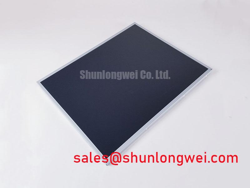
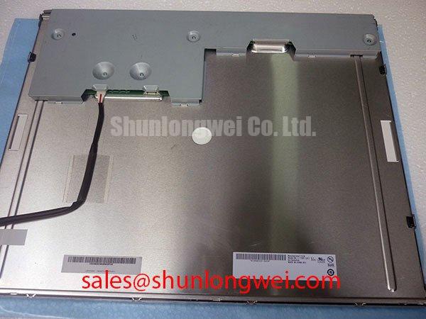
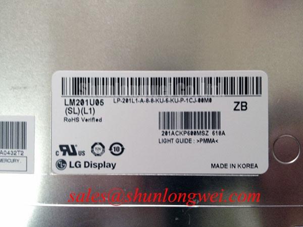
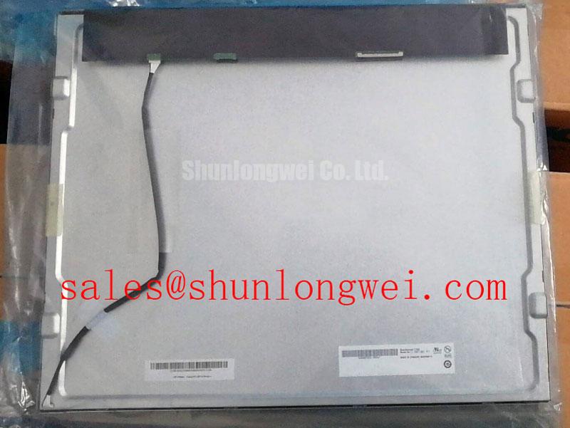
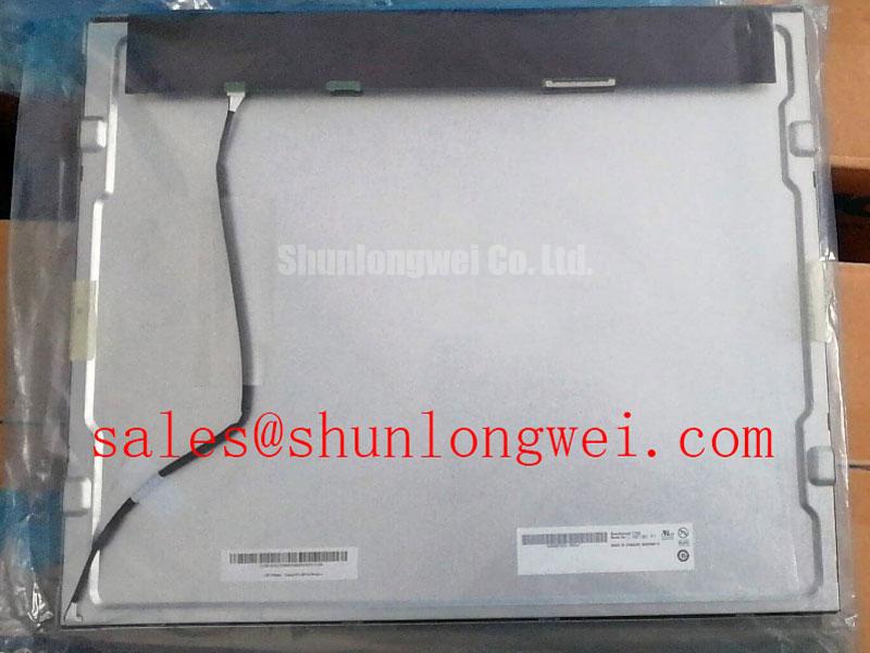
Before installing G190EG02-VG, inspect the panel frame, FPC connection area, sealing surfaces, and mounting supports, then compare the identification label with the original equipment documentation and approved display interface.
The AUO G190EG02-VG is identified in the supplied factory context as an industrial grade LCD and HMI panel in a TFT LCD display module format. The available official information confirms the manufacturer, product category, module construction, and factory specification status. Detailed values for resolution, luminance, viewing angle, interface mapping, supply voltage, backlight architecture, operating temperature, and mechanical dimensions should be verified against the original AUO documentation for the exact production revision before electrical integration.
This distinction is important in a petrochemical operator station or hazardous-area monitoring terminal. A display module may be mechanically compatible while still requiring a different controller, cable map, backlight driver, or environmental qualification. The module itself should not be treated as independently certified for a complete Zone 2 assembly. Equipment integrators must evaluate the complete enclosure, power system, wiring method, thermal design, and applicable site certification requirements.
Begin replacement work with power removed from the host display system. Disconnect the cable only after the supply has been isolated and the stored energy in the display electronics has been assessed according to the equipment maintenance procedure. Record the existing connector orientation, cable bend path, clamp position, and strain relief arrangement before removing the original module. These details often determine whether a replacement panel survives vibration service, even when the display image appears normal during a short bench test.
The supplied factory data does not confirm whether this exact G190EG02-VG revision uses a particular LVDS, RGB, or other video interface, nor does it confirm a 3.3 V or 5.0 V logic supply. The system integrator should verify the required supply voltage, connector pin assignment, enable sequence, and signal mapping from the original panel documentation or the equipment service schematic. Applying a commonly used voltage because it is present on a similar display can damage the timing controller or create an intermittent start-up condition.
Where the host system uses high-speed differential signals, route the replacement cable along the original controlled path and avoid sharp folds near the connector. A differential pair should retain the impedance and pair geometry specified by the controller and panel documentation. A nominal 100 ohm differential target may apply to some display architectures, but it is not an official electrical specification for this product based on the information supplied here. Cable construction, connector type, trace geometry, and controller output standard must therefore be checked as one signal path rather than evaluated from the panel model alone.
Image faults should be diagnosed by measurement rather than by assuming a failed LCD cell. A split image, unstable picture, missing color group, or intermittent start-up may result from incorrect data mapping, incomplete connector insertion, insufficient cable retention, power sequencing, or signal integrity degradation. Compare the suspected channel with a known-good unit where available, inspect the locking mechanism, and use the equipment maker’s approved waveform limits when an oscilloscope check is required.
JEIDA and VESA mapping should not be interchanged without confirming the controller configuration. The correct mapping is determined by the panel revision and its companion electronics. If the display operates with incorrect color order, displaced image data, or unstable synchronization, confirm the documented mapping before changing firmware or modifying cable conductors.
Cold commissioning also requires care. Liquid crystal response can become slower as the display assembly approaches the lower end of its qualified temperature range, but the actual operating range for this model is not included in the supplied factory parameters. A heater strip, enclosure heater, or controlled warm-up routine may be considered only after the system designer verifies condensation risk, thermal uniformity, insulation clearances, and the panel manufacturer’s permitted conditions. Do not infer a guaranteed cold-start performance from a different AUO display family.
⚠️ Maintenance Note: Check the vibration pad, cable clamp, and connector locking condition during scheduled service; a loose support can transfer cyclic stress into the FPC and cause intermittent image loss without visible damage.
Backlight Output, Thermal Control, and Service Life Evidence
Evaluate luminance at the complete assembly level rather than judging the panel only by a brief visual inspection. Record the host controller settings, ambient lighting, display content, and backlight control state when comparing a replacement with the removed unit. A visible brightness difference can originate in the driver current, optical stack condition, controller settings, aging of the original assembly, or a mismatch between display revisions.
The supplied official information does not state whether this exact module uses an LED or another backlight architecture. It also does not provide a rated luminance value, a backlight current, a thermal resistance, an L70 or B50 value, or a 50,000 hour service-life claim. These figures must not be assigned to the G190EG02-VG without the relevant AUO specification or an applicable technical report. If the original equipment uses a separate constant-current driver, verify its output requirements against the actual replacement module before connection.
Thermal inspection is useful when the display is installed in a sealed operator station. Measure the temperature distribution around the display frame, controller board, connector area, and adjacent enclosure surfaces under representative brightness and ambient conditions. Local heating can accelerate optical aging, alter adhesive behavior, or increase the risk of condensation during a later cool-down cycle. Any aluminum spreader, heat rail, gasket, or bracket added by the integrator should be positioned so that it does not load the active area or obstruct the manufacturer’s intended ventilation path.
Industrial cabinets frequently combine vibration, restricted airflow, dust, oil mist, and rapid temperature changes. The sealing interface should be inspected for compression uniformity and hardening. A deteriorated gasket can allow contamination to reach the front surface or create a pressure point against the display frame. When cleaning, use a method approved for the panel surface and avoid solvents that may attack coatings, labels, adhesives, or elastomeric seals.
PWM dimming requires system-level validation. The requested range from 200 Hz to 1 kHz may be relevant to a particular control architecture, but it is not confirmed as an official requirement or limit for this model. The integrator should verify the backlight driver’s PWM input type, amplitude, duty-cycle behavior, minimum pulse response, and electromagnetic compatibility with the installed controller. If visible flicker, beat patterns, or acoustic noise occurs, inspect the driver waveform and grounding arrangement rather than attributing the symptom to the LCD panel alone.
Long-term luminance claims should remain tied to documented evidence. The G190EG02-VG information supplied here does not establish an L70/B50 value, MTBF, or a guaranteed operational lifetime. Maintenance planning should therefore use measured brightness trends, operating temperature records, and the equipment manufacturer’s replacement policy. A service interval can be defined after the site has collected representative condition data, but it should not be presented as a factory-rated lifetime for the module.
For broader enclosure, sealing, thermal, and HMI integration considerations, engineers can consult the Industrial Display & HMI Solutions engineering guide. It should be used as application guidance, while model-specific electrical limits remain subject to the original AUO documentation.
Polarizer Condition, Viewing Performance, and Cold-Environment Inspection
Inspect the front optical surface under the same lighting conditions used at the operator station. Look for scratches, pressure marks, localized discoloration, coating damage, and contamination that remains after approved cleaning. Direct industrial lighting can make surface defects appear more severe than they are, while a dark test screen may reveal nonuniformity that is difficult to see during normal control operation.
The supplied factory parameters do not confirm whether the G190EG02-VG uses TN, IPS, MVA, or another liquid-crystal mode. They also do not provide a viewing-angle specification, grayscale inversion limit, optical retardation value, or anti-glare treatment description. These characteristics should be confirmed from the exact AUO datasheet rather than inferred from the panel size or intended industrial use.
When the display is viewed from an operator position that changes vertically or horizontally, evaluate the actual installed angle and lighting environment. A panel can appear acceptable during a straight-on bench inspection but show contrast loss, color shift, or grayscale changes after installation behind a window or at an inclined cabinet face. The correct assessment should include the normal viewing zone, the brightest nearby light source, and the screen content used by operators.
Polarizer and surface coating damage can be aggravated by pressure from an improperly fitted bezel. Check that the bezel contacts the mechanical frame only where intended and that mounting supports do not press directly against the active display area. Vibration isolation should control movement without creating a concentrated load. If the panel shows a persistent bright or dark region after installation, remove mechanical pressure from the bezel and repeat the inspection before concluding that the LCD itself has an electrical defect.
Cold-environment testing should be performed gradually. Allow the module and enclosure materials to reach equilibrium before applying full operating conditions, and monitor for condensation when equipment moves between a cold outdoor location and a warmer cabinet interior. A heater or anti-condensation function may be considered by the system designer, but its control method must be validated against the panel’s documented operating and storage limits. The supplied data does not authorize a specific temperature range or heater setting for this model.
FPC routing is part of optical reliability as well as electrical reliability. Keep the cable supported along its intended route, prevent it from rubbing against a metal edge, and preserve the connector’s insertion direction. Repeated flexing at the same point can change contact stability over time. The correct bend allowance and retention method should be taken from the cable and connector documentation rather than estimated from the visible width of the FPC.
For a neutral comparison during procurement, engineers may review the M185XW01 VE listing as a separate display option. Any substitution requires confirmation of dimensions, mounting pattern, optical performance, connector assignment, timing requirements, backlight drive, and environmental ratings. Similar appearance or screen size alone is not sufficient evidence of interchangeability.
Acoustic Noise, EMI Control, and Hazardous-Area Integration
Investigate audible buzz with the display operating in the same brightness and refresh conditions used in the cabinet. First separate mechanical vibration from electrical noise by checking the enclosure panel, mounting bracket, cable restraint, and nearby power components. A sound that changes with brightness or image content may be associated with the backlight driver or power conversion circuit, but this cannot be confirmed from the LCD model number alone.
The supplied factory information does not confirm a CCFL backlight, LED driver topology, PWM dimming ratio, ignition voltage, acoustic emission limit, or EMI performance for the G190EG02-VG. Do not apply a high-voltage CCFL ignition assumption or a 1000:1 LED dimming claim to this model without the original technical documentation. The appropriate replacement driver is determined by the actual module revision and the host system architecture.
EMI evaluation should cover the complete display assembly, including the controller, cable harness, backlight electronics, cabinet bonding, and power supply. A display module cannot independently claim compliance with complete equipment standards such as CISPR or EN 55011. The system designer should test conducted and radiated behavior in the final enclosure, with the cable routing and grounding arrangement fixed as they will be in service.
When a differential display interface is present, keep the cable away from high-current switching conductors and maintain the original shield termination method where it is documented. Avoid adding an unverified shield connection at both ends if the equipment grounding design does not support it. Signal integrity and EMC performance should be assessed together because a cable change that improves one measurement can create a ground-current path elsewhere.
For a petrochemical Zone 2 operator station, the complete assembly requires a documented suitability assessment covering enclosure construction, certified components, temperature class, ingress protection, cable entries, bonding, and maintenance procedures. The AUO G190EG02-VG should be treated as the display module within that engineered system, not as independent hazardous-area certification. Before release to service, confirm the module’s exact electrical and environmental ratings, validate the display under the intended cabinet conditions, and retain the revision-specific documentation with the maintenance record.