Content last revised on June 26, 2026
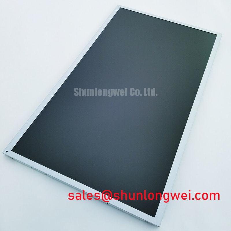
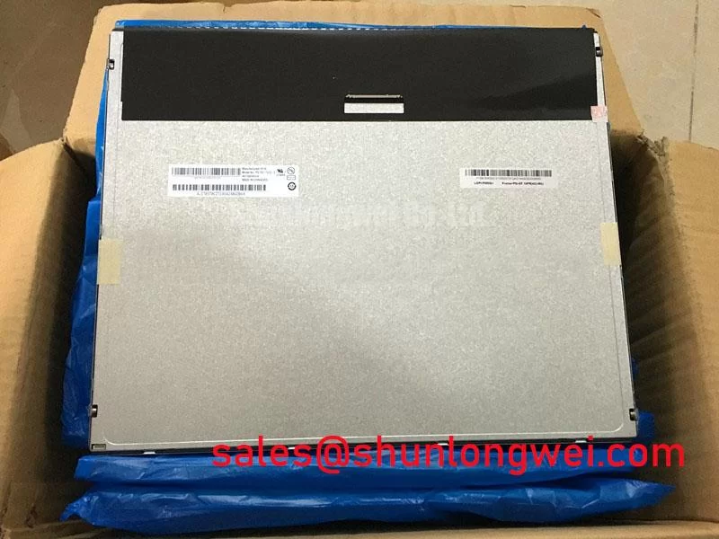
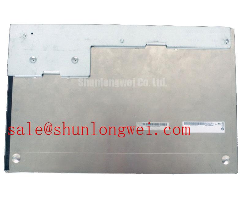
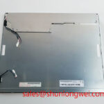
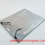
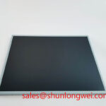
AUO M190EG01 V0: A Deep Dive into this 19-inch Industrial SXGA Display
Key Parameter Overview
Decoding the Specs for Visual Performance and Integration
The AUO M190EG01 V0 is engineered for applications demanding consistent and reliable visual output. Its specifications are tailored to deliver stable performance in various industrial and commercial environments. The combination of a traditional 5:4 aspect ratio with solid optical characteristics makes it a durable choice for legacy system upgrades and new designs requiring this specific form factor.
Best Fit: For industrial control panels and ATM systems requiring a robust 19-inch SXGA display with wide viewing angles and high contrast, the M190EG01 V0 is an excellent engineering choice.
| Feature | Specification |
|---|---|
| Display Technology | a-Si TFT-LCD, P-MVA, Normally Black |
| Resolution & Size | 1280x1024 (SXGA) on a 19.0-inch diagonal |
| Brightness & Contrast | 300 cd/m² (Typ.), 1300:1 (Typ.) Contrast Ratio |
| Viewing Angle | 89/89/89/89 (Typ.) (CR≥10) |
| Color Performance | 16.7M colors, 72% NTSC (CIE1931) |
| Interface | LVDS (2 ch, 8-bit), 30 pins |
| Backlight System | 4 pcs CCFL with 50,000-hour lifetime |
| Operating Temperature | 0°C to 50°C |
| Surface Treatment | Antiglare, Hard coating (3H) |
Download the M190EG01 V0 datasheet for detailed specifications and performance curves.
Application Scenarios & Value
System-Level Benefits in Industrial and Public-Facing Displays
The M190EG01 V0 is particularly well-suited for deployment in environments where off-axis readability and long-term operational stability are critical. Consider an industrial process control HMI mounted on a factory floor. Operators may need to view the screen from various angles while monitoring machinery. The P-MVA technology with its 89° symmetrical viewing angles ensures that critical data—such as pressure readings or alarm states—remains clear and accurate without color shift, regardless of the operator's position. This directly enhances situational awareness and reduces the potential for misinterpretation.
What is the primary benefit of its P-MVA technology? Consistent image quality and color fidelity from wide viewing angles. The high 1300:1 contrast ratio further enhances this, providing deep blacks and bright whites that make text and graphics highly legible even in challenging ambient lighting. Unlike a standard TN panel, which might wash out when viewed from the side, the M190EG01 V0 maintains its integrity, a crucial factor for multi-user interfaces or public information kiosks. For applications demanding different resolutions or sizes, the related G170EG01 V0 offers a 17-inch alternative with the same SXGA resolution.
Frequently Asked Questions (FAQ)
What does the "Normally Black" display mode of the M190EG01 V0 signify for an application?
"Normally Black" is a characteristic of the P-MVA panel technology. It means that when a pixel is in its off state (no voltage applied), it appears black. This contributes to the panel's high native contrast ratio of 1300:1, as it can produce a deeper, more authentic black level compared to "Normally White" technologies like TN. For an engineer, this translates to superior image depth and text legibility, especially in dark-themed user interfaces common in industrial controls.
How does the 50,000-hour CCFL backlight lifetime impact the total cost of ownership (TCO)?
A 50,000-hour backlight lifetime, equivalent to approximately 5.7 years of continuous 24/7 operation, is a significant reliability metric. For systems intended for long-service life, such as ATMs, medical equipment, or factory automation, this extended lifespan minimizes the need for costly maintenance and panel replacements. It reduces downtime and labor costs, making the initial investment in a robust panel like the M190EG01 V0 more cost-effective over the long term compared to displays with shorter-lived backlights. Explore more on the importance of display longevity in our guide to industrial vs. consumer displays.
Is the LVDS interface of the M190EG01 V0 suitable for high-noise industrial environments?
Yes, the Low-Voltage Differential Signaling (LVDS) interface is inherently robust against electromagnetic interference (EMI). It uses two wires with opposing current/voltage swings to transmit data, allowing the receiver to reject common-mode noise that might be induced by nearby motors, power lines, or inverters. This makes the LVDS Interface a reliable choice for connecting the display to a controller board within a complex industrial machine, ensuring signal integrity and a stable image.
Mechanical Robustness & Environmental Resilience
Engineered for Stability and Longevity
The M190EG01 V0 is constructed with durability in mind for its intended applications. The panel's front surface is treated with an antiglare finish and a 3H hard coating. This combination serves a dual purpose: it diffuses ambient light to reduce reflections and improve readability, while also providing a significant level of protection against scratches and minor impacts that are common in public-facing or industrial settings. The physical dimensions of 396 x 324 x 17.5 mm and weight of around 2.5 kg provide a sturdy frame that aids in secure integration into kiosks, panel PCs, or rack-mount systems. The specified operating temperature range of 0°C to 50°C ensures reliable performance in controlled indoor environments, from climate-controlled command centers to factory floors not subject to extreme temperature fluctuations.