


Content last revised on September 10, 2026
Preventing Frame Lag & Image Smearing in Cryogenic Storage & Outdoor Industrial Facilities
When a display is removed from equipment operating near cold storage areas, outdoor cabinets, or high temperature process zones, the first practical task is to separate panel behaviour from system signal problems. A delayed image, intermittent frame update, faint picture, or motion smearing can originate in the host board, video cable, interface timing, backlight circuit, display controller, or the panel itself. It should not be assigned to one cause without comparative measurement.
For the AUO M190EG01 V1, the available product identification does not establish a certified operating temperature range, response time, liquid crystal mode, or thermal cycle qualification. Engineers should therefore verify the environmental limits printed in the original equipment documentation before evaluating use in cold or outdoor industrial equipment. Temperature suitability cannot be inferred from the industrial product category alone.
Design Consideration: temperature changes can affect visible response behaviour and can also expose weaknesses in signal routing, connectors, and enclosure sealing. During a controlled service inspection, compare the panel output with a known stable source and check whether the abnormality changes after the equipment reaches its normal operating condition. Check the display harness for strain, incomplete insertion, contact contamination, and routing near high current switching conductors.
A digital display interface requires a coherent clock and data relationship at the receiving panel. If the host system uses differential signalling, the cable assembly and board routing should preserve pair symmetry, continuous return paths, and controlled impedance appropriate to the original interface. The panel documentation must be used to determine the actual interface type and signal format. Do not assume that a connector with a similar physical appearance uses the same pin assignment or electrical standard.
💡 Pro Tip: Keep each differential pair routed as a matched pair with a stable reference path, then verify clock and data integrity against the known good signal path before attributing image instability to the panel.
Where replacement planning requires comparison with another industrial display family, the M185XW01 VE can be reviewed as a separate reference item. Its suitability must be established through documented comparison of active area, resolution, interface format, backlight arrangement, mounting geometry, and power sequencing rather than nominal screen class alone.
Grayscale Inversion Mitigation & Viewing Direction Alignment
Grayscale inversion, contrast shift, colour variation, and directional visibility should be assessed at the installed viewing position rather than from a single bench angle. For diagnostic, monitoring, and control equipment, the operator’s line of sight is influenced by bezel depth, display tilt, ambient lighting, screen protector layers, and the position of the equipment within its enclosure. A panel that appears acceptable at a direct viewing angle may show different tonal behaviour when evaluated from the normal operator location.
The confirmed product information for the M190EG01 V1 does not specify a liquid crystal mode, viewing direction, viewing cone, contrast ratio, luminance, surface treatment, or anti glare finish. It is therefore inappropriate to classify this model as TN, IPS, MVA, normally white, or any other optical mode without the original AUO documentation. These properties are panel specific and should be checked before a display is selected for image sensitive equipment.
Design Consideration: visible inversion or uneven grayscale may be related to the panel’s optical design, but it can also be influenced by incorrect timing, unsuitable source scaling, unstable supply conditions, mechanical stress, or an optical layer fitted by the equipment manufacturer. A useful service sequence begins with a known correct test image, followed by comparison of the existing video path and the replacement path under the same source settings. Observe neutral gray patterns, fine text, uniform white, and dark field images from the intended installation angle.
High ambient illumination changes perceived contrast even when the panel is operating normally. The enclosure window, cover lens, bonding arrangement, and any protective film can introduce reflections or alter visual uniformity. System integrators should evaluate the complete optical stack in the final enclosure. The module’s product category does not provide a basis for claiming a specific anti glare treatment or readability performance.
Backlight control also requires attention during integration. The M190EG01 V1 identification data supplied here does not confirm the backlight electrical input, dimming method, control polarity, or dimming frequency. The system integrator should verify the required supply voltage, driver topology, enable sequence, and brightness control method from the original panel documentation. A dimming signal should be evaluated with the specified driver and the complete display assembly, particularly where flicker perception or audible driver noise is a concern.
Backlight Thermal Management and Optical Assembly Preservation
Inspect the rear housing, side rails, backlight connections, and enclosure contact surfaces before diagnosing a brightness loss. Uneven brightness, edge shadows, intermittent illumination, or a display that remains visible only under external light can indicate a fault in the backlight supply path, connection system, driver board, panel optical assembly, or thermal interface between the display and the host chassis. These symptoms require measured checks rather than a single assumed failure mechanism.
The available official identification does not state the M190EG01 V1 backlight technology, luminance rating, LED configuration, backlight current, backlight lifetime, light guide material, or thermal limits. No claims should be made about edge lit construction, high brightness capability, LED lifetime, L70 performance, B50 performance, or optical material stability without the model specific factory datasheet.
Design Consideration: if the original equipment documentation confirms that the installation uses an illuminated panel assembly, heat should be allowed to leave the display area through the mechanical structure intended by the equipment designer. A distorted rear cover, missing bracket, compressed cable, blocked ventilation route, or uneven chassis contact can change local temperatures and mechanical loading. These conditions should be inspected before installing another module.
Do not apply thermal pads, adhesive films, metal rails, or conductive tape directly to unknown panel surfaces without confirming the mechanical stack from the equipment documentation. Such additions can create pressure points, interfere with insulation spacing, obstruct service access, or alter the intended enclosure fit. Where a host chassis includes a dedicated thermal contact feature, inspect it for flatness, cleanliness, and correct engagement with the original assembly method.
For repair work involving a dim or unlit screen, verify the incoming display supply, control signals, and backlight driver output according to the original service information. An oscilloscope comparison against a functioning unit can help identify whether the condition is related to enable timing, dimming control, intermittent wiring, or the display assembly. Avoid energising a panel with an assumed backlight voltage or assumed connector pinout.
For broader integration principles covering panel interfaces, optical evaluation, environmental planning, and common selection errors, consult The Ultimate Guide to Industrial TFT LCD Technology. The guide supports process planning but does not replace the model specific documentation required for this AUO module.
Fastener Torque and Mechanical Stress Control
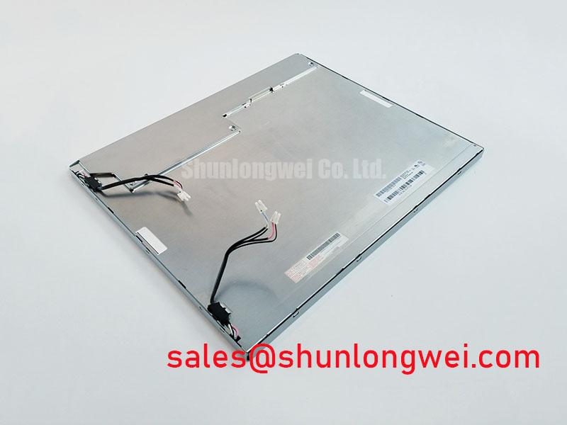
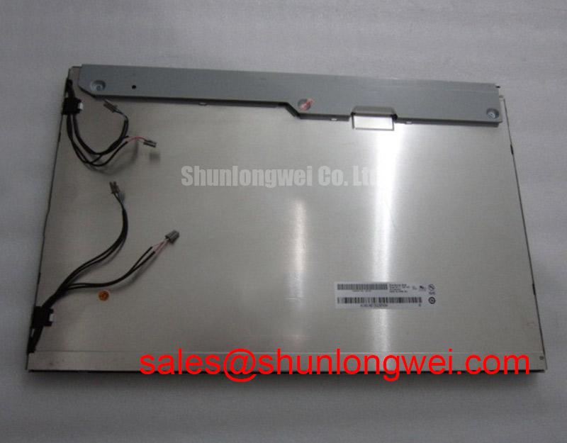
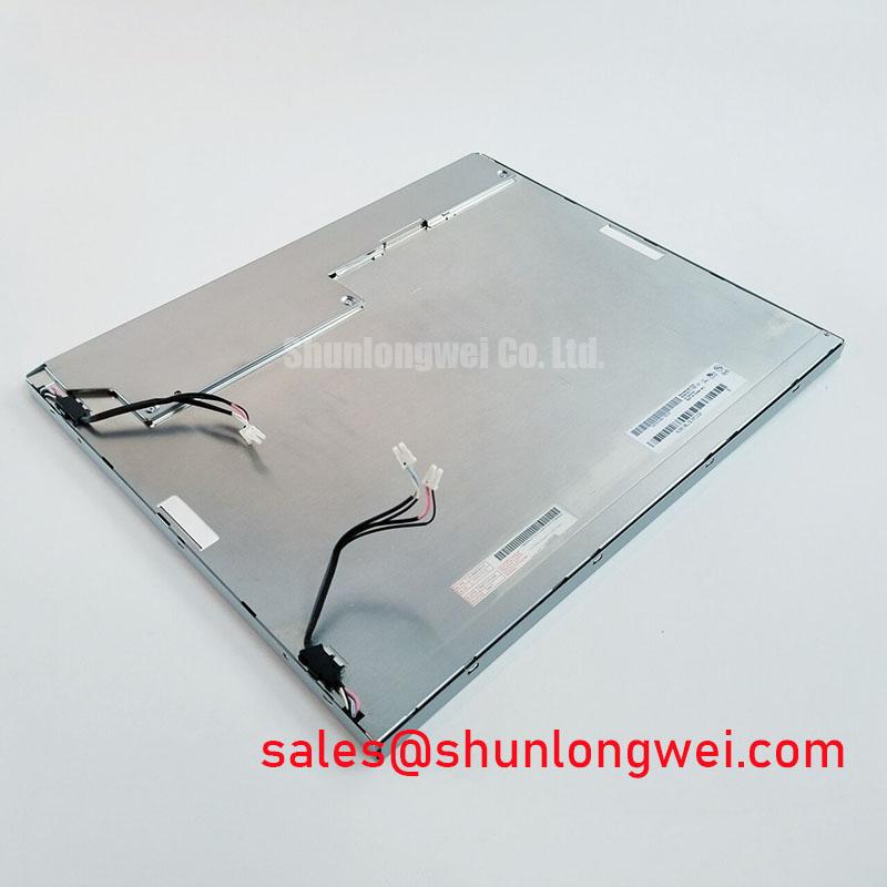
Before fastening the M190EG01 V1 into a replacement bezel, place the module in the intended mechanical position without force and verify that the connector, cable bend path, mounting holes, rear clearance, and front opening align naturally. A display module should not be pulled into position by screws, pressed into a restrictive opening, or used to correct a warped bracket. These conditions can place uneven load on the display assembly and can complicate diagnosis of visible nonuniformity.
The available factory identification does not provide mounting hole dimensions, bezel envelope, fastener size, fastening torque, panel thickness, flatness requirement, or permissible mechanical load for the M190EG01 V1. The specified M3 torque range in a generic installation brief cannot be represented as an AUO requirement for this model. The system integrator should obtain the original mechanical drawing and service procedure before defining a fastening method.
Design Consideration: use a balanced fastening sequence when the original mounting arrangement employs multiple screws. Tighten progressively across the mounting pattern while checking that the module remains seated without twist. The final fastening level must be determined by the original mechanical design, the approved fastener hardware, the bezel material, and the panel manufacturer’s mechanical limits.
After assembly, inspect the display with uniform white, gray, and dark field test images. Localized bright areas, dark regions, colour variation, or pressure marks may indicate mechanical interaction, but they can also be associated with the display source, video settings, cover window, or panel condition. Release and recheck the surrounding chassis interfaces only under an approved service procedure, then compare results with the original mounting condition.
For potential use in surgical navigation or ultrasound diagnostic display terminals, compatibility assessment should include documented confirmation of the original interface, electrical sequencing, optical requirements, mechanical fit, enclosure construction, and applicable equipment level compliance. The M190EG01 V1 product identification alone does not establish medical device approval, diagnostic image suitability, or system safety compliance.