Content last revised on September 26, 2026
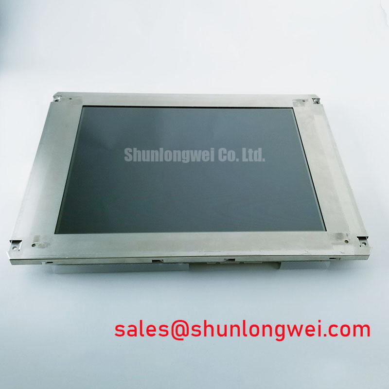
LM190E08-TLGE LG Display Industrial LCD Panel
Begin a replacement inspection by comparing the panel label, connector orientation, mounting envelope, and visible glass condition with the removed unit before applying power. The LM190E08-TLGE is identified in the supplied factory context as an Industrial Grade LCD/HMI Panel manufactured by LG Display, with a TFT-LCD Display Module package and an official factory specification status. The available product record does not provide a complete electrical pinout, display resolution, operating voltage, interface assignment, backlight specification, or mechanical drawing, so those values should be confirmed against the original panel documentation before installation.
For repair engineers, this distinction matters. A panel can have the correct diagonal class and still be unsuitable if its power sequence, signal mapping, connector pitch, mounting holes, backlight control, or bezel depth differs from the removed assembly. Treat the part number as the primary identity reference, then verify the complete system interface at the equipment level.
Display Cable Routing and Signal Integrity Checks
The display signal path should be checked before the replacement panel is connected. Inspect the cable for crushed sections, sharply folded areas, contamination at the connector, and signs of uneven clamping near the panel edge. A known-good cable and the original controller documentation provide a more reliable reference than assumptions based on the product category alone.
The proposed integration context refers to differential display routing and a nominal 100-ohm characteristic impedance. This is a Design Consideration for the system interconnect, not an independently verified factory parameter of the LM190E08-TLGE. The system integrator should confirm whether the installed controller uses LVDS, TTL, or another display interface, together with the applicable data mapping. JEIDA and VESA mappings are not interchangeable assumptions; an incorrect mapping can produce abnormal colors or tonal gradation even when the panel itself is functional.
Power sequencing also requires confirmation from the original equipment documentation. The supplied product information does not verify a 3.3 V or 5.0 V panel supply, a specific rise-time window, or a defined reset sequence. Designers should measure the original panel’s power rails, enable signals, and display clock with an oscilloscope, then compare the replacement installation under controlled conditions. A white screen, delayed image, or residual image after shutdown may involve sequencing, controller configuration, backlight control, or signal integrity, so the symptom should not be assigned to one cause without measurement.
Where pulse-width modulation is used for brightness control, the system integrator should verify the required dimming method and frequency from the original backlight driver documentation. The supplied factory record does not confirm a PWM frequency range or duty-cycle linearity for this model. Any proposed PWM control window should therefore be treated only as an application-level Design Consideration requiring acoustic, optical, and electromagnetic verification in the completed assembly.
For a compatible subsystem comparison, engineers may review NL192108JC18-03ND as a separately listed display reference. It should not be treated as an automatic substitute. Resolution, interface, mounting geometry, optical stack, controller timing, and backlight requirements must be matched from the equipment documentation.
Viewing-Angle Checks for Multi-Angle Consoles
Multi-angle operator consoles require an optical inspection under the actual viewing positions used by the equipment. Check the image from the center, upper, lower, left, and right positions while displaying neutral gray, white, red, green, and blue test fields. This helps separate viewing-angle behavior from cable faults, gamma configuration, backlight nonuniformity, or mechanical pressure on the display assembly.
The supplied factory data identifies the LM190E08-TLGE as a TFT-LCD display module, but it does not confirm a Super-IPS or MVA cell structure, a symmetric 85° viewing specification, a contrast ratio at 50,000 lux, or a specific anti-glare treatment. Those values must not be presented as official parameters for this part without the original LG Display datasheet. If the replacement is being evaluated for a marine radar or navigation bridge console, the complete assembly should be checked for sunlight readability, visor geometry, surface reflections, and salt-contaminated viewing conditions.
As a Design Consideration, a wide viewing cone can support shared displays viewed by operators from different positions, but the practical result depends on the panel optical characteristics, protective window, touch layer, polarizer condition, and enclosure angle. A protective cover can alter reflection and perceived contrast even when the LCD module is operating correctly. The equipment engineer should evaluate the installed stack rather than relying on a generic IPS or MVA classification.
High ambient illumination also changes the visual test method. Use controlled test images and record whether shadow detail, mid-gray transitions, and warning colors remain distinguishable from the normal operating positions. A contrast value quoted for one laboratory condition should not be treated as a guaranteed field result in direct sunlight. The original panel documentation should be checked for luminance, contrast, viewing angle, surface finish, and temperature conditions before making a like-for-like procurement decision.
The same approach applies to gamma and grayscale performance. If a T-CON or controller board is retained, verify that its timing configuration and gamma settings correspond with the replacement panel. If the controller is changed, confirm the complete signal format rather than adjusting the image by trial and error. A color cast or crushed gray scale can result from configuration mismatch and does not, by itself, establish a panel defect.
Mounting and Gasket Considerations for Display Integration
Before fastening the module, place it in the intended opening without forcing the glass, frame, or connector area into alignment. Compare the physical envelope, mounting-hole locations, connector clearance, visible area, and bezel overlap with the removed unit. The supplied factory specification confirms the package as a TFT-LCD Display Module, but it does not provide outer dimensions, bezel tolerances, mounting-hole data, gasket compression limits, or an approved fastener torque.
These missing mechanical values must be taken from the applicable factory drawing or the original equipment service documentation. A flush-mounted panel should be supported evenly around its perimeter so the chassis carries installation load rather than the glass or active display area. The gasket should form a continuous environmental interface without folding across the visible region or placing a hard point against the panel edge.
Uniform fastening is a Design Consideration because uneven mechanical loading may change the optical appearance of an LCD. Dark areas, bright patches, or localized nonuniformity after installation can have several possible sources, including pressure distribution, frame distortion, cable interference, temperature gradients, or an optical assembly issue. Inspect the image before final tightening and again after the equipment reaches its normal operating temperature.
The supplied integration brief mentions an M3 cross-pattern fastening approach and a 0.35 to 0.45 N·m range. This is not confirmed as an LM190E08-TLGE factory installation specification. If the original service documentation provides that value for the surrounding chassis, follow the equipment manufacturer’s procedure; otherwise, the system engineer should determine a controlled fastening method through mechanical validation. Maintenance Note: Check the perimeter gasket and cabinet airflow during scheduled service so dust ingress, moisture accumulation, and uneven thermal loading are identified before they affect image quality.
For harsh environments, sealing should be assessed at the enclosure level. The LCD module alone should not be described as salt-fog proof, watertight, or independently certified for a marine installation unless a relevant manufacturer document states so. A navigation console may require an external window, gasket, conformal protection, drainage path, and corrosion-control measures selected by the equipment designer. The applicable integration principles are also discussed in Industrial Display & HMI Solutions.
Thermal management should be checked after the mechanical installation is complete. Confirm that the rear of the module is not blocked by cable loops, insulation, or a mounting bracket. Measure temperature distribution around the enclosure during representative operation, paying attention to areas near the backlight driver and power conversion hardware. The factory information supplied for this product does not specify a backlight thermal map or a permitted hot-spot value, so the completed equipment must be evaluated using its own environmental and operating limits.
As a separate display reference, LQ201U1LW31 may be reviewed when comparing module options. It is a distinct product record and should not be assumed to be a required companion or compatible driver for the LM190E08-TLGE.
Preventing Mechanical Stress and Diagnosing Display Faults
Start a bench diagnosis with a three-step primary-color test using full-field red, green, and blue images, followed by white, black, and neutral-gray screens. Observe the display from normal viewing distance, then use a flashlight at approximately 45 degrees to inspect dark-field shadows, edge discoloration, and localized bands. This method can help distinguish a backlight distribution problem from a signal, controller, or glass-edge condition, but it cannot identify a specific internal failure without further testing.
Do not press the glass, driver-bond area, or flexible circuit while the panel is operating. Instead, compare the image while gently observing cable movement outside the display boundary and monitor the controller signals with suitable probing methods. A change caused by cable movement may indicate an interconnect or mechanical routing issue, while a stable localized defect may require panel-level service evaluation. These observations are diagnostic clues rather than proof of a single failure mode.
The supplied factory record does not confirm the internal driver-bond construction, TTL or LVDS transmitter limits, clock-jitter margin, data hold time, or industrial temperature timing window of this model. Those parameters should be obtained from the original technical documentation. If the equipment uses LVDS, verify pair order, polarity, termination arrangement, clock presence, and controller configuration against the known-good assembly. If it uses TTL, confirm the voltage domain and timing definitions from the system schematic rather than applying an LVDS assumption.
Temperature testing should be performed gradually and with the panel mounted in its intended mechanical condition. Record startup behavior, image stability, color transitions, and backlight response at the equipment’s specified environmental points. The available product record does not establish a specific operating temperature range or lifetime rating, so no service-life conclusion should be drawn from a short bench test. Any intermittent behavior should be correlated with connector condition, power stability, enclosure temperature, and mechanical restraint.
When procurement teams compare alternatives, retain the exact model identity and request the relevant factory documentation for every candidate. A same-size panel can still require a different controller, cable, backlight driver, mounting method, or optical stack. The LM190E08-TLGE should therefore be evaluated as an LG Display TFT-LCD Display Module within the complete HMI assembly, with electrical, optical, mechanical, and environmental compatibility verified before field replacement.