

Content last revised on September 10, 2026
Logic Supply Voltage Sequencing and Driver IC Latch-Up Risk Assessment
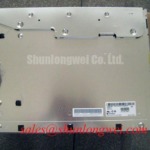
Before connecting the LM201U05-SLL1 to an AGV or forklift telematics controller, the system integrator should verify the required logic supply voltage from the original panel documentation. Do not assume that a similar-looking TFT-LCD module accepts the same voltage as another display in the equipment. A controller that applies signal activity before the panel logic rail is stable can create abnormal start-up behavior, including incomplete initialization, unstable image output, or stress on interface devices.
A practical bench check starts with the panel disconnected from the vehicle controller. Confirm the connector keying and pin numbering from the panel documentation, then inspect the supply and ground paths for unintended continuity to signal pins. When power is applied through a current-limited laboratory source, monitor the rise of the logic rail and the timing relationship between power enable, reset, backlight enable, and video activity. The supplied technical context references a possible 3.3 V or 5.0 V sequencing evaluation, but the correct value for this model must be verified from the applicable LG Display documentation rather than inferred from the model family.
LVDS compatibility also requires more than confirming that a connector is present. The receiver must align with the transmitted pixel data arrangement, differential clock behavior, color depth, and mapping convention. JEIDA and VESA arrangements can place color bits differently even when the physical cable appears compatible. A mapping error may produce incorrect colors, split-screen artifacts, missing grayscale steps, or an image that shifts during initialization.
As a Design Consideration, differential pairs should be routed as controlled-impedance paths with consistent reference planes and minimal discontinuities. The supplied engineering target references approximately 100 Ω differential impedance and a skew budget of no more than 50 ps; these are system-level integration targets, not confirmed factory specifications for the LM201U05-SLL1. The final routing, termination, and timing margin should be validated on the assembled controller and cable harness, particularly where servo drives, traction inverters, or wireless equipment share the enclosure.
When a replacement panel shows intermittent image loss, compare the differential clock and data waveforms with a known-good signal path instead of assigning the fault to the display immediately. Probe loading, cable shielding, connector contact pressure, ground offsets, and controller configuration can all influence the result. If the equipment uses TTL rather than LVDS, the integrator should verify the required interface from the original panel documentation because the product description supplied here does not confirm a TTL interface.
For a same-size or same-resolution replacement assessment, engineers can also review NL192108JC18-03ND as a separate display option. It should be treated as an independent compatibility candidate, with connector, timing, mounting, and backlight requirements checked individually.
Backlight Driver Noise and EMI Evaluation across 200 Hz to 1 kHz PWM Frequencies
Backlight diagnosis should begin by identifying the actual illumination architecture in the original assembly. The available product information confirms a TFT-LCD Display Module but does not confirm whether this specific unit uses a CCFL assembly or an LED backlight, nor does it publish a verified ignition voltage, dimming ratio, operating frequency, or lifetime figure. The system integrator should therefore verify the backlight type, connector pinout, enable logic, current control method, and protection behavior from the original panel documentation.
A CCFL-equipped system may require a dedicated inverter, while an LED-equipped system normally depends on a suitable constant-current driver. These are not interchangeable power interfaces. Applying an inverter output to an LED input, or connecting a constant-current source to an unverified backlight connector, can damage the panel assembly and the controller. During a repair evaluation, disconnect the backlight from the logic board where the design permits, inspect the harness, and test the driver separately according to its own documentation.
Acoustic noise from a display assembly can originate in the driver, transformer, capacitor, mounting frame, or enclosure resonance. It should be evaluated with the complete panel and driver installed in the same mechanical condition used by the equipment. A change in PWM frequency may alter audible behavior, visible flicker, conducted emissions, and the apparent response of the backlight. The supplied engineering scope mentions a 200 Hz to 1 kHz evaluation range, but this range is not an official LM201U05-SLL1 specification. It is a Design Consideration for system-level testing only.
In a factory environment, measure conducted and radiated disturbance with the display cable routed as it will be in the vehicle. Keep high-current traction wiring physically separated from low-level display harnesses where the enclosure allows, and verify shield termination at the intended chassis reference. A display module cannot independently claim compliance with whole-equipment EMC standards. Any CISPR, EN 55011, or equivalent evaluation applies to the completed system, its enclosure, wiring, grounding, and operating modes.
Temperature can change the visual response of the liquid crystal layer and the electrical behavior of the backlight driver. At low ambient temperature, image transitions may appear slower and the display may require a longer stabilization period after power-up. This does not establish a guaranteed operating range for this model. When the panel is considered for an outdoor AGV or forklift display, designers should verify the rated temperature limits, storage limits, condensation control, optical performance, and enclosure sealing from the original factory documentation.
💡 Pro Tip: Disconnect power before inserting or removing the display cable, then verify the connector orientation and locking action before the next powered test.
Single Vertical Hairline Defect and Sub-Pixel Column Driver Open-Circuit Localization
A vertical line should be documented before the panel is removed from the equipment. Photograph the symptom with a white screen, black screen, and primary-color screens, then note whether the line remains fixed while the image content changes. This three-condition comparison helps separate a panel-side pixel or column-driver symptom from a video-source, cable, or timing problem without relying on an unsupported single-cause diagnosis.
For a controlled bench test, use red, green, blue, white, black, and mid-gray patterns generated by a known-good controller. Observe the line from a normal viewing position and then inspect the panel surface with oblique illumination. A 45-degree flashlight inspection can reveal surface marks, edge damage, pressure points, or shadows caused by the optical stack, but it cannot by itself confirm an internal driver defect. Do not press the glass or flex the bonded edge while the panel is powered.
If the line is present in every test pattern at the same column, the result may indicate a panel-side signal or column-related issue. If it changes with cable movement, input content, or controller reset, continue checking the signal path before authorizing a panel replacement. Compare the input waveform and connector contact condition with a known-good assembly. A missing differential pair, impedance discontinuity, poor ground reference, or incorrect data mapping can create image defects that resemble a display-cell fault.
When a defect appears only after mechanical installation, inspect the bezel opening, frame flatness, screw loading, cable bend, and connector strain. The external mounting structure should support the module without transferring concentrated force to the glass or bonded edge. The correct clearance and fastener method are determined by the equipment housing and the panel mechanical drawing; they should not be guessed from the product name.
Backlight faults require a separate observation. A dark region that follows the illumination area rather than the pixel column may point toward the driver, harness, or backlight assembly, while a line that remains tied to image coordinates may require panel-side investigation. Use the driver’s documented fault output where available, and measure only within the voltage and current boundaries specified for that driver. The LM201U05-SLL1 product data supplied here does not publish a verified fault-diagnostic output or backlight protection profile.
For broader enclosure, vibration, grounding, and HMI integration considerations, the Industrial Display and HMI Solutions engineering resource provides a useful system-level reference. It should complement, not replace, the original panel drawing and controller documentation.
Aluminum Heat Spreader Sizing and Thermal Interface Placement along Narrow Display Edges
Thermal evaluation should be performed after the display is mounted in the actual bezel or a representative fixture. Record the temperature distribution across the panel frame, controller area, backlight driver, and nearby enclosure surfaces while the display operates through representative image patterns. A narrow edge can retain heat when the housing blocks airflow or when the driver is positioned close to the optical assembly, but the required thermal solution depends on the complete mechanical design.
An aluminum spreader rail may be considered when heat must be distributed toward a larger chassis surface. This is a Design Consideration, not a confirmed construction feature or thermal rating of the LM201U05-SLL1. The spreader should contact the intended structural area without loading the glass, blocking the active area, shorting exposed conductors, or interfering with the flex cable. Any thermal pad, insulator, or interface compound must be selected for dielectric behavior, compression, aging, and compatibility with the enclosure materials.
Do not infer an LED lifetime, L70 value, B50 value, or half-life MTBF for this model from general display industry practice. No such field-life or factory lifetime data is included in the supplied specification. If the panel is proposed for an AGV or forklift telematics display, the equipment manufacturer should verify the complete backlight lifetime calculation under actual brightness, duty cycle, ambient temperature, vibration, and enclosure conditions.
PWM dimming should be evaluated together with camera interaction, human visual comfort, acoustic behavior, and driver response. The referenced 200 Hz to 1 kHz range may be used as a system test range where supported by the selected driver, but it is not a published LM201U05-SLL1 rating. Duty-cycle linearity, minimum usable brightness, start-up behavior, and fault recovery must be confirmed with the selected backlight controller.
Optical surface requirements also belong to the complete equipment design. A high-brightness warehouse display may need glare control, a protective window, or an anti-glare and anti-reflection treatment, but the supplied factory data does not confirm an AG or AR surface on this model. Check viewing conditions, cover-window spacing, seal design, sunlight exposure, touch overlay compatibility, and cleaning chemicals before finalizing the bezel. If a resistive or capacitive touch layer is added, verify glove operation, water response, controller compatibility, and mechanical stack-up independently from the LCD module.
The LM201U05-SLL1 is therefore best evaluated as an LG Display TFT-LCD industrial HMI module whose final suitability depends on documented electrical interfaces, backlight requirements, timing configuration, and mechanical fit. For overseas repair and sourcing teams, preserving the original panel documentation and matching each interface item before installation provides a more reliable decision path than selecting by appearance or connector shape alone.