Content last revised on October 21, 2026
LTM09C015K LCD Panel Inspection and Replacement Checks
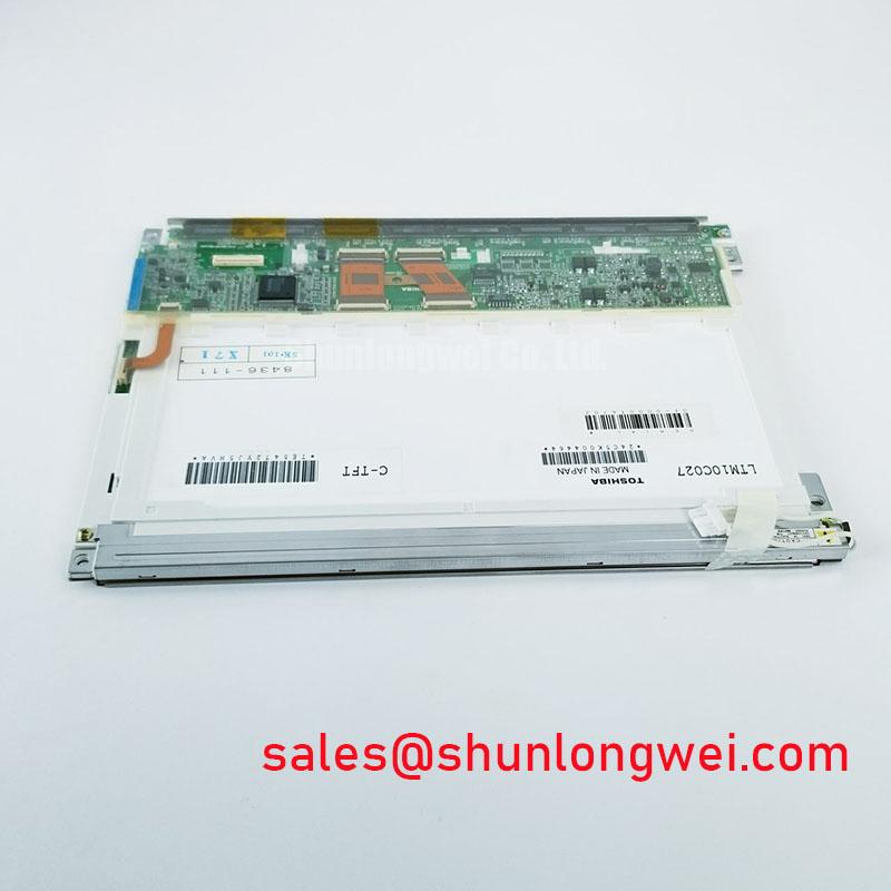
When a CNC operator panel or robot teach pendant shows a dark screen, begin with the installed display disconnected from power and inspect the panel surface and connector seating. Evaluate pixel response only during a controlled powered test after confirming the electrical requirements. The listed unit is the LTM09C015K LCD display module. Confirm its manufacturer and full model designation against the panel label and original equipment documentation before selecting a replacement.
Before applying power, match the replacement against the original equipment documentation, including the display interface, logic supply requirement, backlight arrangement, mounting envelope, and connector orientation. The model identity alone should not be used to infer an unlisted voltage, pin count, pixel format, or backlight drive method. This discipline prevents a physically compatible panel from being connected to an electrically incompatible controller.
Backlight Driver Compatibility, Dimming & Flicker Checks
Backlight evaluation should start with a uniform white field, followed by low-brightness gray screens where flicker, edge shading, or unstable illumination is easier to notice. In a WLED-backlit system, a constant-current driver can provide predictable LED current regulation, while PWM brightness control is determined by the driver and controller combination rather than by the basic TFT designation alone.
A 1000:1 PWM dimming target and a PWM frequency range such as 200 Hz to 1 kHz are system-level design considerations, not confirmed factory specifications for this listing. When integrating the LTM09C015K, the engineer should confirm the backlight architecture and, where PWM control is used, the driver’s PWM input polarity, frequency window, duty-cycle behavior, enable timing, and open-load response from the original panel documentation. The display should be observed with a photodiode or high-speed camera when low-duty operation is important, since recorded modulation can vary with camera exposure, ambient light, and driver topology.
Acoustic noise should be checked at minimum and intermediate brightness settings. Audible buzz may originate from the driver, mechanical mounting, or enclosure resonance rather than from the LCD cell itself. If the original assembly uses a different backlight architecture, the replacement evaluation should include connector pinout, current regulation behavior, thermal rise, and fault output compatibility. A claimed half-life or MTBF value must come from the relevant panel or backlight datasheet; it should not be assigned to the LTM09C015K from a generic LED service-life figure.
Managing Localized Thermal Gradients and Optical Color Shift
Localized heating along a narrow display edge can create visible brightness and color differences, so the first mechanical check is contact pressure around the bezel, driver board, and backlight frame. The LTM09C015K should sit evenly in its enclosure without a clamp, gasket, or cable pressing against the active viewing area. Designers should provide a continuous thermal path where the equipment structure requires heat spreading, while avoiding pressure that can distort the display assembly.
Aluminum heat-spreader rails are a general design consideration for reducing concentrated temperature gradients in an enclosure. Their dimensions, contact method, and insulation requirements must be established from the complete mechanical stack-up. Do not assume that a rail, thermal pad, or conductive bracket is part of the panel specification. The practical acceptance test is a warmed display showing white, gray, red, green, and blue fields while the technician checks for edge-to-center changes and repeatable color drift.
Signal timing deserves a separate check during the same temperature sweep. TTL or LVDS transmitter clock stability, data hold time, cable strain, and receiver margin are properties of the panel-controller link. An oscilloscope comparison with a known-good assembly can help distinguish timing instability from optical nonuniformity. The LTM09C015K listing does not establish a specific LVDS mapping, clock rate, or logic voltage; the system integrator should use the original panel documentation before selecting a transmitter or cable.
For broader enclosure practices covering industrial HMI assemblies, the Industrial Display & HMI Solutions engineering guide provides useful system-level context. Optical inspection should also account for the viewing stack: LCD polarizers and optical glass influence contrast, reflections, and color perception, as described in this LCD polarizer and optical glass reference.
Checking for Mechanical Stress on Dark Screen Fields
Dark-field inspection is the quickest way to reveal mechanical stress that remains invisible on a bright screen. Display the panel at low brightness with a near-black image, then inspect the corners, connector edge, and areas beneath the bezel. Bright patches, crescent-shaped shading, or pressure marks should be compared with the panel removed from the chassis so that enclosure loading is not mistaken for an electronic defect.
Chassis clearance, bezel flatness, gasket compression, and screw alignment should be treated as a combined tolerance problem. A cross-pattern fastening method is a general installation practice, while any exact screw torque must come from the panel or equipment mechanical specification. The commonly suggested torque values for small display fasteners must not be presented as an LTM09C015K factory requirement. Use a calibrated driver only after confirming the fastener size, thread engagement, washer arrangement, and enclosure material.
LED service-life curves are also system-dependent. A reference such as 50,000 hours to a stated brightness percentage belongs to a documented backlight test condition, including current, temperature, duty cycle, and acceptance threshold. It should not be treated as an unconditional operating-life promise for this model. For replacement approval, record brightness uniformity at installation and repeat the same image sequence after thermal stabilization.
⚠️ Field Alert: Disconnect power before reseating the display cable, and keep the flex cable flat and fully aligned before locking its connector.
Verifying the Display Interface, Pixel Clock & Signal Timing
Interface work must begin with the original controller documentation and a pin-by-pin comparison, not with connector appearance. The available information for this product does not confirm a 20-pin or 30-pin connector, a particular LVDS mapping, or a specific logic supply. The replacement assessment therefore needs the original cable, controller board, connector keying, backlight enable path, and panel identification label checked together.
For a differential display link, controlled routing and consistent pair geometry are design considerations used to limit reflections and skew. A nominal 100-ohm differential characteristic impedance is a common interface design target, but the correct value and termination arrangement remain system-dependent. Split-screen images, swapped colors, missing columns, or unstable synchronization may indicate an incorrect mapping, timing relationship, cable fault, or supply-sequencing issue. Compare the suspect assembly with a known-good signal path using an oscilloscope and verify pixel clock, data alignment, and enable timing at the controller output.
Power-on behavior should be checked in the order required by the original panel documentation. Do not assume that a 3.3 V or 5.0 V logic rail applies to this model without confirmation. Any specified rise-time window, reset delay, or backlight-enable sequence belongs to the controller-panel combination. The technician should also inspect the connector for uneven insertion, damaged contacts, contamination, and cable bend stress before changing software timing.
For CNC operator panels and robot teach pendants, sunlight testing should use the actual cover window and enclosure geometry. Contrast, glare, and viewing angle can change substantially under direct illumination. Anti-glare and anti-reflection treatments are optical system attributes; a Mini-LED local-dimming architecture, for example, is a separate backlight approach described in this Mini-LED reference and should not be attributed to the LTM09C015K without supporting documentation. Engineers researching other displays can review TCG070WVLPCANN-AN00 as a separate display option and verify its interface and mechanical data independently; it is not established here as a compatible replacement.