Content last revised on October 20, 2026
LM201U05-SLM1 Replacement Evaluation
- Confirm the replacement identity as LM201U05-SLM1 from the panel label and service record.
- Check the chassis opening, edge support, connector orientation, and rear clearance before removing the installed display.
- Review the original panel documentation for supply sequencing, video interface, backlight architecture, and control signals.
- Inspect the display harness and insulation condition before applying power to the replacement panel.
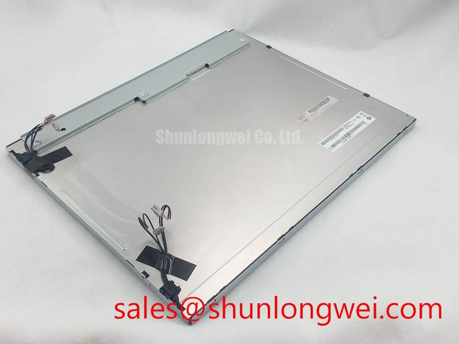
LM201U05-SLM1 is an LG Display TFT LCD active matrix color display module classified for industrial HMI and panel integration. Its decoded baseline specification identifies a standard form factor, while the precise electrical interface, optical ratings, backlight arrangement, and mechanical drawing must be matched with the original equipment documentation.
| Product category | Industrial Grade LCD/HMI Panel |
| Manufacturer | LG Display |
| Package or housing | TFT LCD Active Matrix Color Display Module |
| Specification status | Decoded Baseline / Standard Form Factor |
| Application check | AGV, forklift telematics, industrial HMI, and control-panel replacement evaluation |
When evaluating this panel for an automated guided vehicle or forklift display, the replacement decision should be based on physical fit, signal compatibility, power sequencing, and backlight control rather than panel size alone. The LM215WF3-SDDF can serve as a separate same-family reference during display sourcing, but it should not be treated as a direct substitute without a complete interface and mechanical comparison.
High-Voltage Striking Potential (1500–1650 Vrms) and Secondary Coil Insulation Testing
A high-voltage cold-cathode fluorescent lamp circuit and a constant-current LED driver require different inspection methods, so the installed backlight architecture should be identified before bench testing LM201U05-SLM1. The stated 1500–1650 Vrms range is a system-level diagnostic consideration for applicable CCFL inverter assemblies, not an official electrical rating for this panel.
For a CCFL-equipped system, inspect the secondary wiring, transformer insulation, lamp connectors, and nearby grounded metalwork for tracking or carbonized contamination. A controlled insulation test should be performed only with the panel disconnected from sensitive logic and in accordance with the equipment service procedure. The test voltage, ramp method, leakage limit, and discharge process belong to the inverter assembly and safety procedure, not to the LCD module identity.
LED backlight systems require a different assessment. The constant-current driver should be checked for stable regulation, enable timing, fault response, and dimming behavior. A proposed 1000:1 PWM dimming ratio is a driver design target that must be verified at system level; it should not be presented as a confirmed feature of LM201U05-SLM1 without the applicable panel documentation. Acoustic noise, visible flicker, or uneven brightness should be assessed with the installed driver, harness, and enclosure together.
Long-term brightness claims also need careful separation. A reference such as 50,000 hours to 50% brightness describes an LED or backlight lifetime test condition when supported by a relevant specification. It is not a confirmed MTBF value for this LG Display module. During service evaluation, record the initial luminance, drive condition, ambient temperature, and duty cycle so that later optical changes can be compared against the same test setup.
The companion display reference LM190E08-TLJ7 may help engineers compare a related display-system topology, but its electrical characteristics must remain separate from the LM201U05-SLM1 evaluation.
Suppressing Localized Thermal Gradients to Prevent Chronic Optical Yellowing
Thermal management around a narrow LCD edge should preserve even support and avoid concentrating mechanical pressure near the active viewing area. A properly designed aluminum spreader rail can distribute heat from nearby driver electronics or enclosure contact points, but its dimensions, contact pressure, and attachment method must be determined from the actual chassis drawing.
Do not assume that an external rail, heater strip, or thermal pad is part of the LM201U05-SLM1 module. These are enclosure-level design considerations. When the display is installed in an AGV or forklift telematics housing, inspect whether sunlight, sealed-panel heat, or adjacent processing electronics creates a local temperature gradient. Compare the center and edge appearance after thermal stabilization rather than judging color from a brief power-on observation.
At sub-zero temperatures, liquid-crystal response can slow and gray-to-gray transitions may appear elongated. A heater control system may be considered where the equipment environment requires it, but its temperature thresholds, sensor location, and ramp profile must be established by the system designer. The display should be evaluated across the intended operating window with representative graphics, because static color fields can conceal transition artifacts.
Optical yellowing, haze, or uneven brightness can also be influenced by enclosure pressure, contamination, adhesive aging, and local heat. A repair inspection should therefore compare the panel before installation, after enclosure assembly, and after thermal cycling. The Winstar industrial TFT-LCD and OLED reference material provides useful background on display module integration and optical considerations without defining the LG Display module’s own ratings.
Incoming Benchtop Inspection: Display Bond and Edge Integrity
Start incoming inspection with full-screen red, green, blue, white, black, and mid-gray images. This primary-color sequence helps separate backlight uniformity problems from pixel-line defects, while a flashlight held at approximately 45 degrees can reveal localized shadows, edge deformation, or surface contamination that is difficult to see under direct room lighting.
COG and TAB regions should be viewed without pressing the glass edge or flex-bond area. A line defect that changes with mechanical pressure requires controlled comparison against the signal path and panel assembly; it should not be assigned to one internal cause from appearance alone. Check for repeating column defects, intermittent lines during warm-up, and changes when the display harness is gently repositioned within its normal service clearance.
If the host uses a differential video link, the routing should preserve pair symmetry, controlled impedance, and a short return path through the connector and cable assembly. The commonly used 100 Ω ±10% differential target and a 50 ps skew budget are design considerations for a particular transmitter and receiver channel, not confirmed specifications of LM201U05-SLM1. Measure the installed channel where signal integrity is questioned, then compare clock quality, eye opening, and data alignment with a known-good system.
JEIDA and VESA data ordering must also be checked at the host transmitter. A panel can show a lit image while still displaying incorrect color order, swapped bit significance, or unstable timing. Confirm the selected mapping and pixel-clock relationship from the original panel documentation before changing firmware or cable wiring. Information on TFT operation can be cross-referenced through TFT LCD technology fundamentals.
💡 Pro Tip: Keep differential pairs physically matched through the connector transition and avoid routing them beside switching-node conductors, because excessive asymmetry can appear as pixel-clock instability during vehicle operation.
Wide Viewing-Angle Considerations for Multi-Angle Consoles
A viewing specification of 85°/85°/85°/85° is an optical evaluation criterion for a wide symmetric viewing cone; it must not be assigned to LM201U05-SLM1 unless the corresponding LG Display documentation confirms it. When a display is used in a multi-angle AGV or forklift console, assess grayscale stability, contrast perception, and color shift from the actual operator positions rather than relying on a single front-facing inspection.
TN, IPS, and MVA technologies can present different off-axis behavior, particularly in dark-gray transitions and high-ambient conditions. Surface treatment also affects readability: glare from warehouse lighting, sunlight, and protective cover glass may be more significant than the nominal viewing angle. The enclosure window, anti-glare layer, bonding method, and display tilt should therefore be evaluated as one optical assembly.
For TTL or LVDS systems, the transmitter clock must remain aligned with the panel’s accepted data timing across the intended temperature range. Verify setup and hold margins with the actual cable, connector, host board, and power sequence. A white screen at startup followed by recovery can involve enable order, reset behavior, backlight timing, or video synchronization; inspect the complete sequence instead of changing one signal without measurement.
When installing the panel behind a sealed industrial bezel, check gasket compression, window alignment, dust paths, and condensation risk. Optical bonding may improve environmental separation when the complete assembly is designed for it, but bonding material, curing process, and serviceability are enclosure decisions rather than confirmed attributes of this display module. Practical repair and integration references are available in The Ultimate Guide to Industrial TFT LCD Technology.