

Content last revised on September 10, 2026
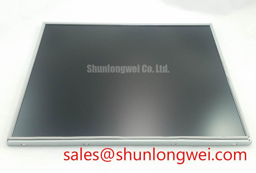
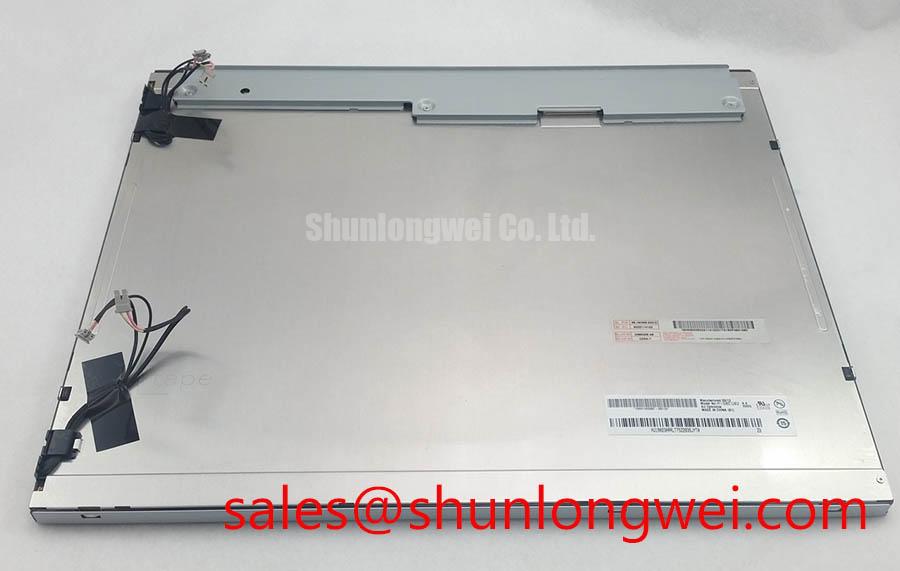
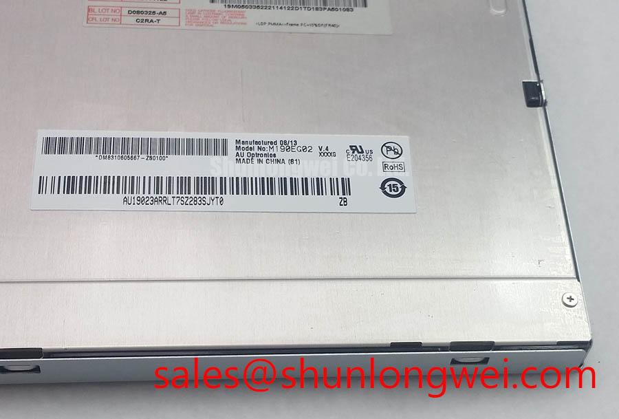
| Model | M190EG02 V4 |
| Manufacturer | AU Optronics (AUO) |
| Product Category | Industrial TFT LCD Module |
| Display Construction | TFT LCD Active Matrix Color Display Module |
| Specification Status | Official Factory Spec Verified |
Chassis M3 Fastener Torque Sizing to Eliminate Optical Mura Defects
Inspect the front bezel contact pattern and loosen the chassis fasteners in a diagonal sequence when a newly installed M190EG02 V4 shows corner brightening, pressure spots, or irregular dark field shading. These visual effects can arise when mechanical load is concentrated at one point of the panel perimeter rather than distributed across the mounting frame.
A controlled 0.35 to 0.45 N·m tightening range for M3 hardware is a Design Consideration for panel mounting rather than an AU Optronics factory torque specification for this model. The applicable torque depends on the screw, thread engagement, bezel material, washer arrangement, and the original equipment manufacturer’s mounting design. Tighten incrementally in a cross pattern, then inspect a dark image and neutral grey image after each pass. This procedure helps reveal whether a visible mura condition changes with mechanical stress.
The outer bezel should support the module evenly without bending the active display area. A distorted chassis, raised gasket seam, trapped cable, or uneven rear support can impose a local force that becomes more visible on low luminance images. Do not correct a light nonuniformity issue by increasing screw torque. Check flatness, edge clearance, and the condition of the protective gasket first.
⚠️ Maintenance Note: Disconnect power before reseating display cables, and inspect the bezel gasket and cooling path during scheduled cabinet maintenance because trapped dust and uneven sealing can add stress or retain moisture around the display assembly.
Cold ambient operation deserves a separate functional check. Liquid crystal response can become slower at subzero temperatures, so a display that appears to smear during a cold start should be observed again after the enclosure reaches its intended operating condition. Any cited minus 30°C to plus 85°C range should be checked against the specific panel documentation and must not be treated as a complete operating specification for every assembled monitor, controller, or HMI enclosure.
Where a system incorporates a heater strip or enclosure heater, its control point must be established by the equipment designer. The objective is stable panel temperature and avoidance of condensation, not rapid heating of one display edge. Verify thermal behavior with the display installed in its actual frame, since a heater located close to a bezel can create local temperature gradients that alter optical appearance.
For long service intervals, review mounting stress after cabinet vibration, transport, or repeated door opening. The panel itself is an Industrial TFT LCD Module, but the installed result depends on the stiffness of the host chassis, the panel support geometry, and the fit of surrounding seals. Engineers evaluating this module for industrial HMI or monitoring equipment should confirm that the original mounting points and mechanical datum surfaces are retained.
Flashlight Dark Shadow Optical Diagnostic to Isolate Logic vs. Backlight Failure Modes
Apply a controlled image source and inspect red, green, blue, white, and black fields before removing the panel when the screen is dark, intermittently lit, or marked by lines. Solid primary fields help separate a source image problem from a panel level defect because each field exposes different channel behavior and makes stuck, missing, or unstable pixel regions easier to observe.
With the unit powered and a valid image commanded, hold a flashlight at approximately 45 degrees to the front surface and look for faint image detail. A faint image can indicate that image data is reaching the active matrix while illumination requires further investigation. It does not by itself establish a single failed part. Check the display power sequence, signal source, cable seating, and the backlight driver path with the instrument methods appropriate to the host equipment.
Horizontal bands, isolated vertical lines, or image disturbance that changes when the bezel is touched require a careful mechanical and electrical inspection. Such symptoms may be associated with a cable path, connector contact, timing board connection, or panel interconnect stress. Avoid flexing the glass or pressing directly on the display face to force a symptom to appear. Compare the signal path against a known good assembly where practical and use an oscilloscope to determine whether the disturbance already exists at the host output.
Backlight aging cannot be assigned a specific remaining service life without controlled field data and the applicable manufacturer documentation. Constant current regulation, enclosure temperature, dust accumulation, and airflow all affect illumination stability. A gradual reduction in apparent brightness should therefore be evaluated together with driver behavior, optical cleanliness, and the original display settings rather than attributed automatically to one internal element.
Power sequencing also matters during diagnosis. An all white image at startup, a residual image during shutdown, or a brief unstable frame can point toward timing order, source initialization, or supply behavior in the host system. Verify that panel power, image data, and enable signals follow the original equipment timing requirements. The system integrator should verify the required supply voltage and sequencing requirements from the original panel documentation and the host controller design.
Static interface pages deserve periodic review in equipment that presents the same alarm, navigation, or process screen for extended periods. Use the software functions available in the host device, such as controlled brightness management or screen refresh behavior, where supported. This is a Design Consideration for the complete terminal, not an asserted factory feature of the M190EG02 V4.
Wide Temperature Operational Margin and Sub Zero Liquid Crystal Viscosity
Cycle the installed display through the equipment’s expected cold and hot states while monitoring image response, uniformity, and any evidence of enclosure condensation. At low temperature, liquid crystal viscosity can increase and grey transitions can appear slower. That behavior should be compared with the host device’s permitted startup routine and expected operating conditions rather than judged from a room temperature bench test alone.
Any cited minus 30°C to plus 85°C thermal window should be verified against the panel’s own environmental specification. It does not replace confirmation of the complete display terminal. The cabinet, front window, touch assembly if fitted, backlight driver, power supply, and cable routing all influence actual panel temperature. An enclosure can be warm internally while the front surface remains cold enough for moisture to form during rapid ambient changes.
Inspect perimeter seals, bezel drainage paths, and enclosure vents whenever recurring haze, intermittent image behavior, or surface contamination is reported. The goal is to prevent moisture ingress and avoid trapping humid air against the display assembly. Optical bonding, if included by the original equipment manufacturer, must be treated as an assembly level construction feature. Do not assume that every M190EG02 V4 integration includes an optically bonded front stack.
Thermal cycling can also expose marginal interface connections. Signal quality should be checked at cold and hot conditions when image noise is temperature dependent. Differential signal traces require controlled impedance, matched routing, and sound return paths as a Design Consideration. The correct impedance target, skew allowance, transmitter jitter tolerance, and data timing margins are determined by the original interface standard and the complete controller to panel connection.
Where wide viewing angles are important for monitoring positions, judge color shift and contrast with the actual protective window and mounting angle installed. Viewing appearance is influenced by the panel, surface treatment, front glass, ambient light, and any polarizing or privacy layers added by the equipment manufacturer. Do not compensate a suspected viewing angle issue by changing timing controller gamma voltages without the original display controller documentation and calibrated test equipment.
For context on enclosure integration, lifecycle checks, environmental sealing, and HMI display maintenance practices, consult Industrial Display & HMI Solutions. The practical value of that assessment is in confirming the completed assembly around the panel, including airflow, front sealing, cable strain relief, and service access.
Shielded FFC FPC Flat Flexible Cable Grounding across 360 Degree Connector Shells
Inspect connector seating, shield continuity, and cable strain relief when pixel jitter or moving horizontal noise bands appear near switched loads in the same cabinet. Begin at the display connector and follow the cable route to the host board, looking for incomplete latch engagement, damaged shielding, excessive bend stress, or a route shared with high energy motor conductors.
A shielded FFC, FPC, or LVDS cable should be terminated according to the original equipment interface architecture. Where the design provides a conductive connector shell and chassis reference, establish the intended broad shield connection rather than adding an improvised drain wire. A 360 degree shell termination is a Design Consideration for controlling common mode interference in compatible cable systems, subject to the connector construction and grounding scheme selected by the equipment designer.
Variable frequency motor drives and other switching loads can couple noise into a display signal path through cable routing, common impedance, or enclosure openings. A ferrite solution may be evaluated when measurements show common mode interference, but component selection and placement require validation on the finished system. Do not assume that a ferrite alone resolves image instability, since an intermittent connector, weak chassis bond, or disturbed power sequence can produce similar visible symptoms.
Use a known good signal source where available, then compare the affected system with the same panel connected through the intended cable assembly. If the image becomes stable, inspect the removed cable for conductor damage and verify shield bonding at both ends according to the host equipment drawings. If noise remains, capture the clock and data behavior at the controller output and at the panel end to determine whether the disturbance is introduced before or along the cable route.
Data hold time, transmitter clock quality, and receiver margin must remain valid across the equipment temperature range. These are system determined characteristics, not published hardware parameters in the available M190EG02 V4 product facts. Engineers should preserve the original interface type, cable construction, connector orientation, and grounding method when carrying out a replacement or repair.
Keep the display cable separate from power switching loops where the cabinet layout permits, while maintaining enough service slack to prevent tension at the panel connector. Recheck image stability after closing the enclosure, because a door, cover, or cable clamp can alter cable position and shield contact. This method supports disciplined isolation of display noise without making unsupported claims about product level EMC compliance.