

Content last revised on October 10, 2026
Incoming Benchtop Inspection: ACF Integrity and Interface Timing
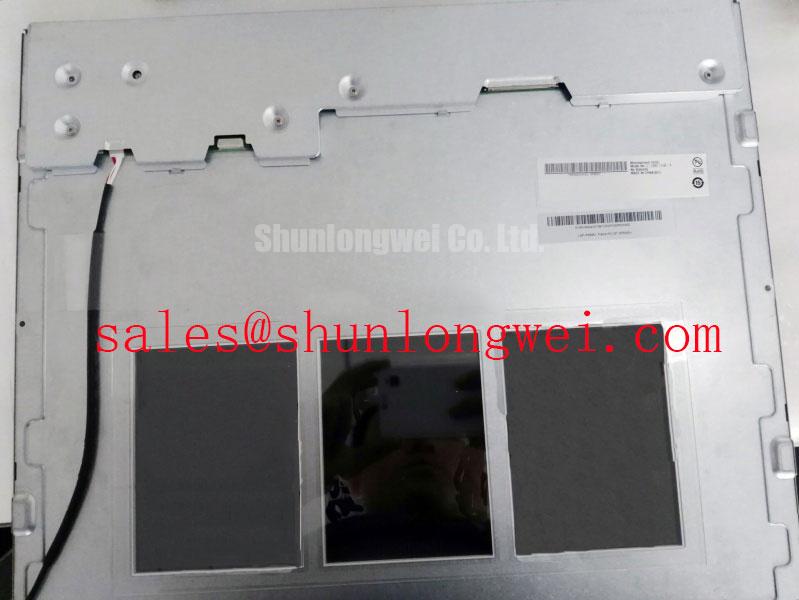
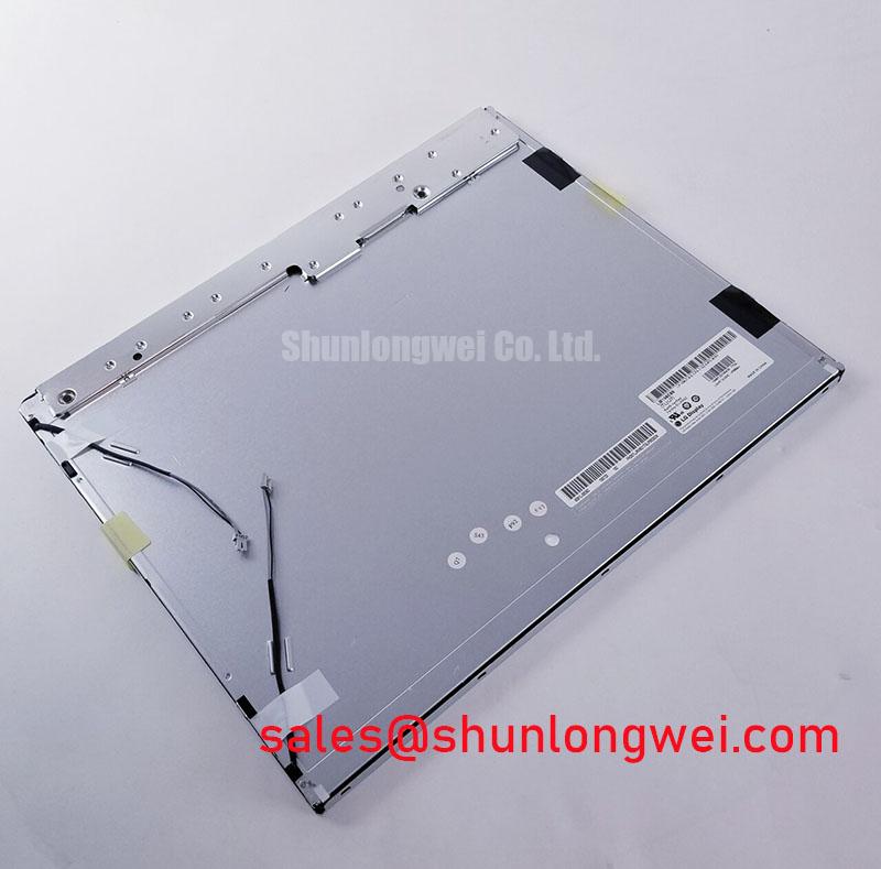
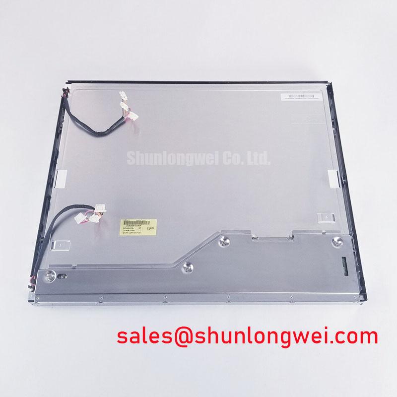
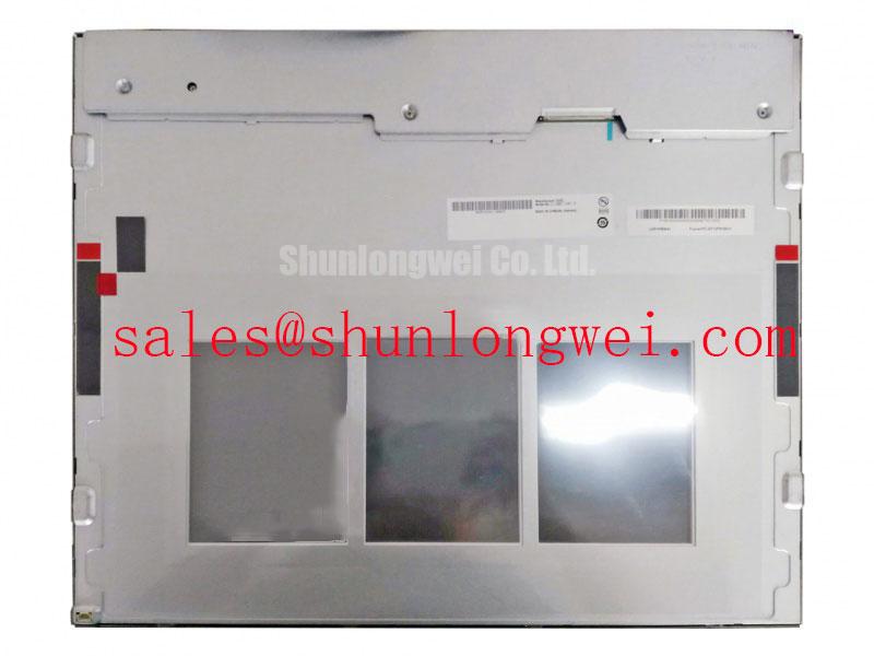
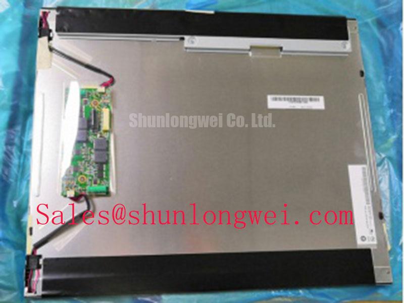
At the incoming bench, isolate the panel from the machine harness, inspect the active display area under controlled illumination, and verify the original interface documentation before applying power. The G190ETN01-6 is an AUO industrial-grade LCD/HMI panel in a TFT-LCD active-matrix color display module format. The available baseline treats it as a standard-form-factor panel; interface voltage, resolution, dimensions, optical values, and backlight electrical ratings should be taken from the matching panel documentation for the installed unit.
Begin the visual assessment with a black image, then apply full red, green, and blue screens in sequence. Uneven vertical lines, fixed columns, edge-band defects, or color-specific interruptions should be recorded by position rather than treated as proof of a single internal failure. A 45-degree flashlight inspection can help separate a dark image caused by missing illumination from a line defect that remains visible in the liquid-crystal layer. The test is most useful in a darkened work area, with the display viewed both directly and at a shallow angle.
COG and TAB bonding areas require non-invasive inspection. Look for lifted edge films, local pressure marks, contamination near the bonded region, and changes that appear when the chassis is gently repositioned without pressing the glass. Do not flex the active area or use the bezel as a lever. If the defect changes with mechanical disturbance, compare the panel against a known-good signal path and document the condition before any connector or mechanical work.
The system interface must be identified before timing measurements are planned. If the host uses LVDS, review differential clock stability, data hold behavior, lane mapping, and panel-side power sequencing over the intended temperature range. If the host uses TTL, confirm the original logic convention and timing table instead of transferring LVDS assumptions to the replacement. Clock jitter, insufficient setup margin, or an incorrect pixel mapping can produce symptoms that resemble a panel fault.
For railway passenger information systems or cab signalling displays, compare the incoming panel’s connector location, active-area orientation, mounting pattern, and cable routing with the removed unit. The M185XW01 V7 may be evaluated as a same-size-class service alternative only after the integrator confirms mechanical, optical, interface, and firmware compatibility.
Cold-Start Response and Thermal-Cycle Integration
Cold-start testing should focus on the time required for text, symbols, and gray transitions to become visually stable after the machine is powered. Liquid-crystal viscosity changes at low temperature can increase gray-to-gray response delay, causing moving characters or status changes to appear soft before the panel reaches its operating condition. Record the behavior at the actual enclosure temperature and distinguish a slow optical response from a delayed source signal or an unstable backlight controller.
| Evaluation item | G190ETN01-6 | M185XW01 V7 service comparison |
|---|---|---|
| Manufacturer | AUO | Panel documentation required |
| Product category | Industrial TFT-LCD active-matrix color display module | Industrial LCD replacement candidate |
| Form factor status | Standard-form-factor baseline; confirm against the installed unit | Confirm against the installed chassis |
| Interface and backlight ratings | Verify from the applicable panel documentation | Verify from the applicable panel documentation |
| Use in railway display equipment | Compatibility evaluation required | Compatibility evaluation required |
The perimeter seal and bezel interface deserve attention during thermal cycling. Uneven compression can create local optical pressure, bezel shadowing, or light leakage that changes as the assembly warms. Use a clean, continuous sealing surface and release mechanical stress evenly across the frame. A replacement panel should not be judged only by connector compatibility; enclosure depth, cable bend radius, viewing direction, and the relationship between the active area and the front window also affect field performance.
Backlight control must be evaluated as part of the complete display assembly. Where the system uses PWM dimming, the integrator should verify the controller’s switching frequency, duty-cycle behavior, startup ramp, and low-brightness linearity against the panel and driver documentation. A poorly matched control signal can produce visible flicker, audible noise, or intermittent startup even when the LCD image data is correct. Backlight open-load, short-load, and over-voltage responses belong to the driver circuit assessment and should not be attributed to the G190ETN01-6 without measured evidence.
⚠️ Maintenance Note: Inspect the cabinet airflow path and the display sealing gasket during scheduled service, because blocked ventilation or a displaced gasket can accelerate optical and mechanical problems.
Polarizer and Surface Performance under Direct Industrial Lighting
Evaluate the display with the same lighting geometry used in the finished equipment. Direct sunlight, LED work lights, and high-bay luminaires can expose reflections, haze, surface contamination, and viewing-angle limitations that are not obvious on a repair bench. Check black, white, and mid-gray screens from the operator’s normal position, then repeat the observation from the practical horizontal and vertical viewing range.
The supplied baseline does not establish a specific TN, IPS, or MVA optical mode, nor does it confirm a particular anti-glare or anti-reflection treatment for this model. Avoid assigning a viewing-cone value or surface coating type without the applicable AUO specification. The Tianma NLT industrial TFT-LCD technology resources and Tianma Microelectronics industrial display resources provide useful industry context for optical evaluation, but they do not establish the specifications of the AUO panel.
Surface cleaning should use a method approved for the installed cover and polarizer. Abrasive cloths, concentrated solvents, and excessive edge pressure can alter the surface appearance or damage the optical stack. When a panel is installed behind a protective window, assess the combined reflection path rather than the bare LCD alone. A glossy cover, air gap, or poorly aligned window may create more visible contrast loss than the panel surface itself.
Backlight aging should be tracked by measured luminance and uniformity under the actual driver conditions. A stated 50,000-hour brightness-maintenance figure must come from the relevant panel or backlight specification; it should not be assumed from a generic LED lifetime curve. Constant-current operation, thermal environment, duty cycle, and optical contamination all influence the observed decay. The maintenance record should therefore retain the test condition, brightness setting, and measurement position.
EMC Integration around Variable-Frequency Drives
When the display is installed near servo equipment or variable-frequency motor drives, begin with cable routing and return-current control. Keep the display cable away from switching-node conductors, avoid unnecessary loop area, and bond the enclosure shielding according to the system’s grounding architecture. Pixel jitter, horizontal bands, or sporadic image disruption can also originate in the host transmitter, connector contact, cable termination, or power distribution.
If the panel interface uses LVDS, the system designer should verify the differential pair impedance, pair-to-pair skew, termination arrangement, and clock-to-data timing against the transmitter and receiver documentation. A commonly used design target is 100 Ω differential impedance with a ±10% tolerance, but this is a system-level engineering consideration rather than an AUO factory specification for the G190ETN01-6. The appropriate skew budget must be established from the interface timing margin and confirmed with probing at the receiver rather than inferred from a visual symptom.
Shield termination should be evaluated at both the display and controller ends, with attention to chassis bonding, connector construction, and the path followed by common-mode current. Ferrite components may be considered where measured interference supports their use, but their impedance behavior must be checked across the disturbance spectrum. Adding a component without reviewing its effect on signal edges and return paths can move the problem rather than remove it.
The LCD module itself should not be represented as independently certified to CISPR Class A or Class B. EMC compliance belongs to the complete equipment, including the enclosure, cable set, power supply, controller, grounding, and operating configuration. For a railway PIS or cab display installation, perform the final emissions and immunity assessment on the assembled equipment with the actual cable lengths and mounting hardware. The industrial TFT-LCD technology guide can provide additional background when reviewing panel selection, optical behavior, and integration constraints.