Content last revised on October 11, 2026
Single Vertical Hairline Defect and Sub-Pixel Column Driver Open-Circuit Localization
Place the panel on a controlled bench, display solid red, green, blue, white, and black test fields, and record whether the vertical line remains fixed while the image content changes. This first separation is important for the AUO G190ETN01-5: a persistent hairline can originate in the display drive path, connector interface, or optical stack, and a single visual symptom does not identify one failed part.
Use the three primary-color sequence before opening the enclosure. A line that remains visible on every field deserves attention at the column-drive path. A line that changes intensity with the background may require comparison across the source image, timing controller output, and panel-side connection. A dark vertical mark that becomes less apparent when the viewing angle changes should also be examined under oblique illumination, because surface reflections and internal optical non-uniformity can resemble an electrical defect.
A 45-degree flashlight inspection is useful after the panel is powered down and isolated. Sweep the light across the affected area while viewing the dark field. A shadow or surface discontinuity that follows the light angle points toward the optical surface, bezel pressure, or contamination. A sharply stable line that is independent of the reflected beam is more consistent with a drive-line or connection issue, although the final distinction requires signal-path testing.
For a host using LVDS or TTL signaling, compare the suspected channel with a known-good channel at the transmitter and then at the panel connector. Do not assume that the presence of a common connector format confirms the same pin assignment or electrical interface. The system integrator should verify the original panel documentation, power sequencing, signal polarity, lane order, and timing controller configuration before applying a replacement.
Clock jitter and data hold behavior should be checked across the equipment’s real operating temperature range. A display that works on a warm bench may show intermittent column activity when cable routing, connector contact resistance, or oscillator timing changes with temperature. Use an oscilloscope with suitable probing practice, preserve the original cable arrangement during comparison, and inspect whether the fault follows the cable, the host output, or the panel input.
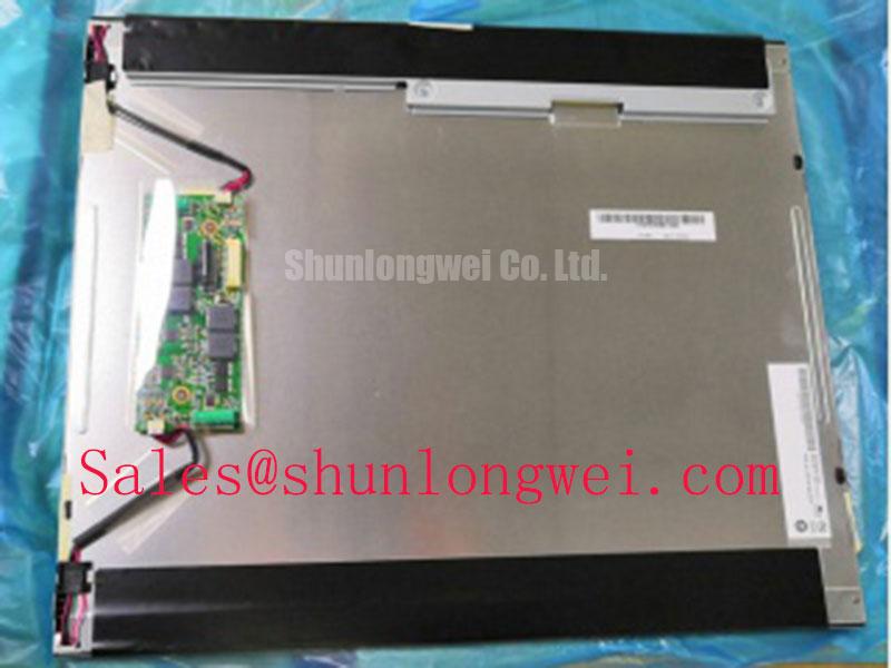
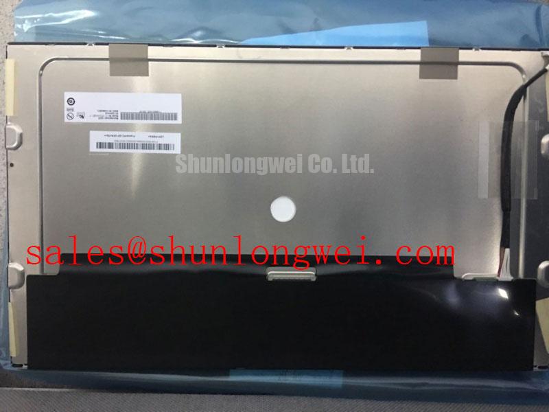
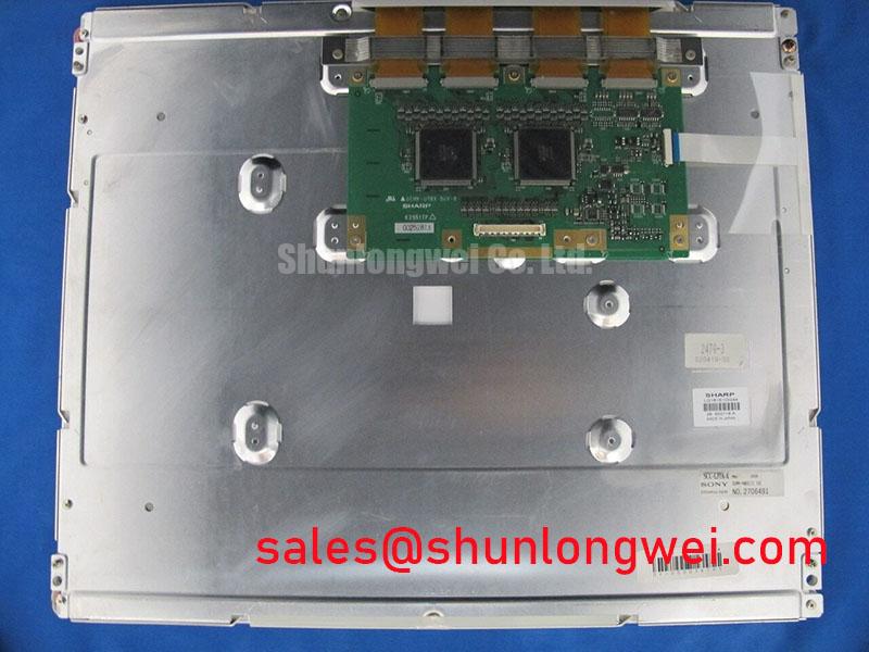
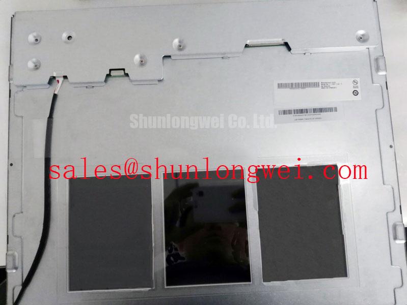
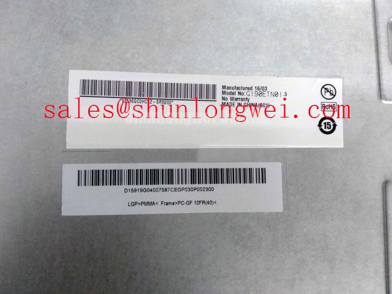
The G190ETN01-5 is identified here as an Industrial Grade LCD/HMI Panel using a TFT-LCD Active Matrix Color Display Module construction. The available product classification is Decoded Baseline / Standard Form Factor; enclosure designers should therefore compare the existing cutout, bezel, mounting points, cable exit, and optical stack rather than relying on the model name alone.
When a same-size or same-resolution replacement evaluation is required, engineers can place NL8048AC19-13 beside the original unit in a controlled compatibility review. This is a neutral cross-model evaluation, not an automatic substitution: connector definition, timing, mechanical envelope, viewing performance, and power requirements remain system-level checks.
Shielded FFC and FPC Flat Flexible Cable Grounding across Connector Shells
Start cable troubleshooting by reproducing the horizontal noise band with the display installed in its normal cabinet position, then separate the display cable from motor-drive wiring and observe whether the disturbance changes. A variable-frequency drive and servo cabinet can couple common-mode energy into an unshielded or poorly terminated display path, but the visible effect can also involve grounding topology, connector contact, host timing, or supply noise.
For a shielded FFC or FPC assembly, the shield should be bonded according to the equipment grounding design at the connector shell or designated chassis interface. Avoid creating an accidental long pigtail that adds an uncontrolled high-frequency path. The purpose of a 360-degree shell contact is to provide a low-inductance enclosure transition; it does not replace a complete cabinet bonding strategy.
Ferrite components may be evaluated as common-mode suppression elements when conducted or radiated interference remains after cable routing and bonding are corrected. Their impedance behavior depends on frequency, current, installation position, and the complete cable geometry. Select them from measured interference data rather than treating a ferrite as a universal cure for pixel jitter.
A differential pair should be routed as a controlled transmission path with consistent spacing and minimal interruption. A 100 Ω differential target is a common design consideration for many LVDS links, but it must be confirmed against the host transmitter, receiver, cable construction, and panel documentation. The target alone cannot correct an incorrect lane map, inadequate return path, or excessive connector discontinuity.
Sub-zero operation adds a separate diagnostic dimension. Liquid-crystal response can slow as temperature falls, so a gray-to-gray transition may appear elongated even when the data stream is correct. Compare a static test image with moving gray patterns, then monitor the panel supply and host timing while the enclosure reaches its intended cold condition. If a heater strip is part of the cabinet design, its control cycle should be assessed for electrical noise, local thermal gradients, and condensation risk rather than assumed to improve every display symptom.
Do not unplug or reconnect the flat cable while the panel or host is energized. ⚠️ Maintenance Note: Inspect cable seating, shell bonding, cabinet airflow, and sealing materials during scheduled service, especially where dust, salt mist, or vibration can affect the connector environment.
For a broader system-level review of display integration in demanding enclosures, see Industrial Display & HMI Solutions. A complementary display-related device such as LQ181E1LW31 may be considered separately when the equipment architecture requires an additional display solution or related interface evaluation.
Chassis M3 Fastener Torque Sizing to Reduce Optical Mura
Release bezel pressure before judging a dark-field mura defect. A panel can show localized brightness variation when the chassis, bezel, gasket, or mounting surface applies uneven mechanical load. The correct service sequence is to document the defect in the installed state, loosen the enclosure evenly, and compare the optical pattern without disturbing the panel cable.
The proposed 0.35–0.45 N·m M3 range should be treated as a project-level design consideration for a suitable chassis fastener arrangement, not as an AUO factory specification for the G190ETN01-5. The final value depends on the bezel material, thread engagement, washer arrangement, gasket compression, mounting-hole geometry, and the mechanical drawing of the host enclosure.
Use a cross-pattern tightening sequence so the bezel settles progressively rather than loading one corner first. Watch the dark field while applying the enclosure hardware. If a bright or dark region changes when one fastener is touched, the mounting stack deserves inspection for burrs, uneven gasket thickness, a distorted bezel, or a chassis surface that is not planar.
Do not compensate for a poor cutout by increasing fastener force. Excessive local stress can change the optical appearance without improving retention, while insufficient support can allow vibration or cable movement. The mechanical engineer should define the outer bezel envelope, clearance, gasket contact area, and fastener sequence from the equipment drawing, then verify the result through thermal cycling and vibration assessment appropriate to the installation.
Cold environments require attention to both mechanical and optical behavior. Materials contract at different rates, and a bezel that appears acceptable at room temperature may impose a different load after the cabinet cools. Condensation control is also part of the installation review. Seal design should prevent moisture ingress while allowing the enclosure thermal strategy to avoid trapped humidity around the display surface and connector region.
For a harsh marine radar or navigation bridge console, salt-laden air, glare, vibration, and repeated maintenance access can affect the bezel interface even when the LCD electronics are functioning correctly. The G190ETN01-5 should be assessed as part of the complete enclosure, including front-surface protection, sealing method, cable strain relief, and service clearance.
Surface Anti-Glare and Anti-Reflective Treatment for High Ambient Readability
Evaluate readability with the actual lighting geometry instead of relying on a dark-room image. Place the display at the intended operator position, introduce the expected overhead and forward reflections, and compare white, mid-gray, and dark test fields. Anti-glare and anti-reflective treatments address different optical problems: surface diffusion can reduce mirror-like reflections, while anti-reflective treatment is intended to reduce surface reflection losses.
The product classification identifies the G190ETN01-5 as a TFT-LCD active-matrix color display module, but it does not by itself establish a particular AG texture, AR coating stack, luminance value, contrast value, or viewing-angle specification. Those characteristics must be matched from the applicable panel documentation and the installed optical system. Avoid describing the unit as having a confirmed 85°/85°/85°/85° viewing cone without a supporting manufacturer specification.
Viewing-angle behavior can change the apparent brightness and grayscale relationship as the operator moves away from the normal axis. The general optical principles are described in Viewing Angle Characteristics in LCDs. For industrial display comparisons, Winstar Industrial TFT-LCD and OLED Display Modules provides useful industry context, but its product data should not be transferred to the AUO model.
When the host uses a T-CON, the grayscale voltage ladder and gamma correction are controlled by the complete panel and timing architecture. A washed highlight, crushed shadow, or color-channel imbalance should be checked against source data, T-CON configuration, supply stability, and cable integrity before any gamma adjustment is attempted. Changing a gamma setting can hide a timing or signal-integrity fault rather than repair it.
TTL or LVDS transmitter timing also affects visible image stability. Check clock quality, data hold behavior, lane alignment, and connector continuity at the operating temperature used by the equipment. The system designer should establish the required timing margin from the actual transmitter, receiver, cable, and panel documentation, then validate the complete path under enclosure lighting and temperature conditions.
For operator consoles, CNC pendants, industrial HMI cabinets, or marine navigation equipment, the front cover and touch interface can dominate usability as much as the LCD itself. If a resistive or capacitive touch layer is added, verify glove operation, wet-finger behavior, cover-glass reflection, controller compatibility, and sealing independently. The G190ETN01-5 listing identifies the display module category; it does not establish a factory-fitted touch function.
Clean the front surface with a method approved for the installed coating and avoid abrasive materials that can alter haze or reflection. In high-ambient installations, compare the display after cleaning, after enclosure assembly, and after the intended protective window is fitted. A protective window, air gap, adhesive layer, or bezel lip can introduce reflections that are absent from the bare panel.