Content last revised on October 23, 2026
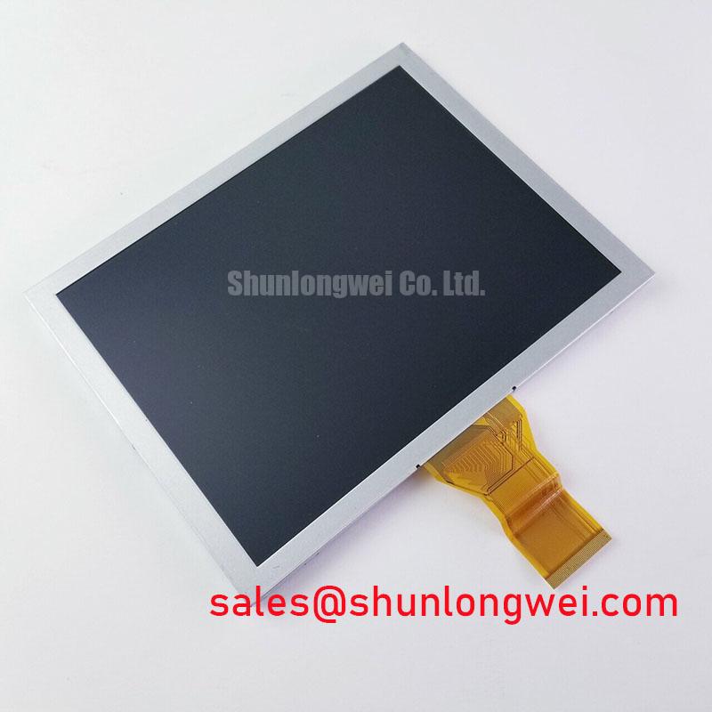
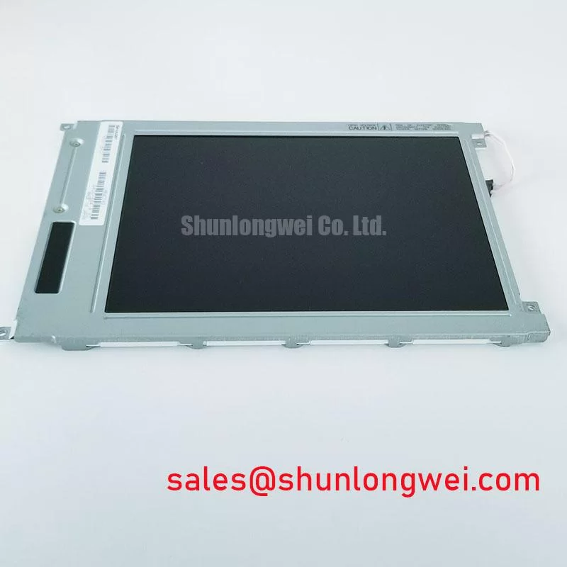
AUO A080XN01 V0 800×480 CCFL LCD Display
- Confirm the panel marking is A080XN01 V0 before removing the installed display.
- Record the existing cable orientation and verify compatibility with the panel’s 60 pin TTL, 6 bit parallel interface.
- Check the enclosure opening, bezel contact points, mounting pattern, and cable bend clearance before fastening the replacement.
- Inspect the separate CCFL inverter, backlight wiring, and display supply path before attributing a dark screen to the LCD panel.
The AUO A080XN01 V0 is an 8.0 inch industrial TFT LCD display with a native 800 RGB × 480 WVGA resolution, a 60 pin TTL interface, and a single CCFL backlight. For equipment repair, the interface and backlight arrangement are the first replacement checks: this panel is not a direct substitute for an LVDS or LED-backlit display without system-level interface and backlight changes.
| Category | Official Specification |
|---|---|
| Manufacturer | AUO |
| Model | A080XN01 V0 |
| Screen size | 8.0 inch diagonal |
| Resolution | 800 RGB × 480 WVGA |
| Brightness | 250 cd/m² typical |
| Contrast ratio | 300:1 |
| Response time | 30 ms, Tr + Tf |
| Viewing angle | 65/65/45/65 degrees, L/R/U/D |
| Interface | 60 pin TTL, 6 bit parallel |
| Backlight | One CCFL lamp |
| Operating temperature | −10°C to +60°C |
| Storage temperature | −20°C to +70°C |
Mechanical Clearance and Mounting Stress in Industrial Metal Enclosures
Mechanical installation should begin with the bezel envelope rather than the screw holes. A metal enclosure can press unevenly against the display perimeter when the cutout is tight, when the chassis is distorted, or when fasteners are tightened in sequence from one side. Check that the glass and bezel sit evenly in the opening, with no point loading transferred from the enclosure to the active area.
A cross-pattern tightening sequence is a useful Design Consideration for reducing localized stress. Where the equipment drawing specifies M3 fasteners, a general starting range of 0.35 to 0.45 N·m may be considered, subject to the original mechanical design and fastener condition. This is not an AUO factory specification for the panel. The system engineer should validate the final torque against the bezel material, gasket compression, screw type, and enclosure flatness.
Dark-field nonuniformity near an edge can be associated with mechanical pressure, optical stack distortion, cable interference, or an electrical image problem. Compare the symptom before and after loosening the enclosure hardware under controlled service conditions, while protecting the panel from movement. Optical bonding, sealing, and anti-vibration parts should be treated as system-level integration choices; they are not listed as built-in features of this model.
The listed interface is parallel TTL, so differential-pair routing rules do not define the panel’s own data connection. Any differential-link impedance and skew requirements elsewhere in the host system must come from that link’s documentation, not from this panel’s 60 pin TTL interface. If a converter board is installed, its signal integrity and grounding require separate validation under the actual factory noise environment.
Single-CCFL Backlight Inverter and Ignition Debugging
The A080XN01 V0 uses one CCFL lamp, which places the inverter and lamp wiring at the center of a dark-screen investigation. Inspect the inverter input supply, enable control, high-voltage lead insulation, connector seating, and lamp socket condition before replacing the panel. A failed inverter can leave the LCD image path functional while producing a completely dark display, so an external light test can help distinguish image generation from backlight operation.
Cold-start ignition behavior depends on the matched inverter, lamp condition, wiring capacitance, ambient temperature, and protection settings. Verify the required ignition voltage against the panel and inverter documentation rather than assuming a generic CCFL value. Likewise, constant-current LED operation and 1000:1 PWM dimming are not established features of its native single-CCFL backlight.
The official operating range is −10°C to +60°C. Storage down to −20°C does not establish powered operating capability at that temperature. At low temperature, liquid-crystal response and CCFL starting behavior can both change, so the repair test should remain within the rated operating range unless the complete equipment manufacturer has qualified a controlled thermal solution. A heater strip must not be treated as a standard panel feature; if used by the equipment designer, its temperature distribution and electrical isolation require independent verification.
⚠️ Field Alert: Disconnect power and allow the inverter circuit to discharge before removing the CCFL connector or the 60 pin display cable.
60 Pin TTL Interface, Pixel Timing & Cable Checks
This model should be checked as a 60 pin TTL, 6 bit parallel display, not as a 20 pin or 30 pin LVDS panel. An LVDS cable, JEIDA mapping, VESA mapping, or differential pixel-clock assumption can produce a blank image, incorrect colors, split-screen artifacts, or unstable synchronization when applied to the wrong interface family.
During replacement, compare the original host board connector keying, pin numbering, signal grouping, ground locations, and control lines with the panel documentation used by the equipment manufacturer. Do not infer a 3.3 V or 5.0 V supply from a generic LCD wiring convention. The system integrator should verify the required logic supply and timing conditions from the original panel documentation and host-board design before applying power.
For a converter or custom interface board, designers should control return-current paths, minimize cable stubs, and confirm the pixel timing at the panel connector with the known-good system. Differential 100 ohm routing is relevant to LVDS sections of such a converter, but it does not convert the native TTL interface into LVDS by itself. The 30 ms Tr + Tf response specification describes panel response behavior; it is not a pixel-clock skew allowance or a timing margin.
When the image is divided, shifted, or color channels appear displaced, compare the installed cable orientation and parallel data order with a functioning unit. A scope comparison at the host connector can reveal missing clock activity, control-line timing differences, or excessive ringing without assigning a single fault to the LCD glass.
Brightness, Viewing Angles & High-Ambient Readability
The listed brightness is 250 cd/m² typical, with a 300:1 contrast ratio and viewing angles of 65/65/45/65 degrees for left, right, up, and down viewing. These figures should be used when assessing readability in an operator console; they do not confirm a special anti-glare or anti-reflective etched coating.
For a replacement in a bright control cabinet or a navigation console, evaluate the installed window, ambient reflections, viewing direction, and display hood together. The unequal vertical viewing angles make the operator’s eye position important, particularly when the panel is mounted above or below the normal line of sight. The Color Gamut Coverage: NTSC vs sRGB vs DCI-P3 reference explains why brightness and color gamut are separate evaluation items, while Display Aspect Ratio and Standard Screen Form Factors provides useful context for image geometry and enclosure layout.
Do not describe this panel as an IPS or MVA display. The supplied specification identifies the viewing-angle performance but does not establish IPS or MVA construction, full symmetric viewing, AG etching, AR treatment, optical bonding, or marine sealing. Engineers evaluating the part for a harsh marine radar or navigation bridge console should verify enclosure protection, window reflection control, salt exposure resistance, and backlight service access at the complete equipment level.
For broader TFT selection, interface planning, and reliability considerations, consult the The Ultimate Guide to Industrial TFT LCD Technology. The A080XN01 V0 remains most suitable for evaluations where the original system specifically requires its 800 × 480 format, 60 pin TTL connection, single CCFL backlight, and rated temperature range.