Content last revised on October 10, 2026
Aluminum Heat Spreader Sizing & Thermal Interface Placement along Narrow Display Edges
| Product | LM190E08-TLH2 |
|---|---|
| Manufacturer | LG Display |
| Category | LCD Display Module |
| Display Technology | TFT-LCD Active Matrix Color Display Module |
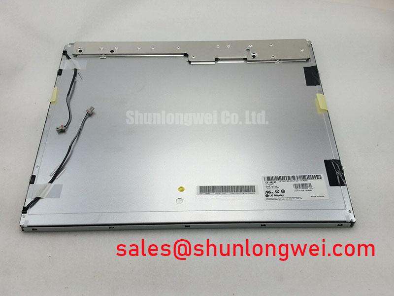
Inspect the display perimeter and mounting interface before fitting an aluminum heat spreader rail, paying particular attention to narrow edge sections where enclosure heat can remain concentrated. The LM190E08-TLH2 is identified as a TFT-LCD Active Matrix Color Display Module from LG Display. Its product category does not, by itself, define the thermal capacity of a complete AGV or forklift display assembly.
A practical Design Consideration is to use edge spreader rails only where they can transfer heat into the enclosure without loading the glass, bezel, flex connections, or optical stack. The rail should sit against a stable mechanical surface, while the interface material remains evenly placed and free from trapped debris. Uneven compression can introduce local stress, visible luminance variation, or assembly distortion. Thermal contact should therefore be checked together with gasket compression and panel flatness rather than treated as a separate electrical task.
Direct sunlight can make a telematics display difficult to read even when the panel is operating normally. For an AGV or forklift enclosure, designers should evaluate the complete optical stack, including cover glass, viewing angle, ambient reflections, and any anti-glare or anti-reflection treatment. A contrast target above 500:1 at 50,000 lux is a system evaluation criterion, not an official specification established here for this model. The same distinction applies to claims concerning PMMA yellowing, LED L70 or B50 performance, and long-term optical stability.
When the panel is installed behind a sealed front bezel, compare the temperature near the display edges with the temperature near the enclosure exhaust path. This helps identify whether heat is being trapped by the gasket, mounting frame, or nearby drive electronics. External industrial display references from Tianma NLT Industrial TFT-LCD Display Technologies and Winstar industrial TFT-LCD modules also illustrate why optical and mechanical integration must be assessed at assembly level.
20-Pin/30-Pin Differential LVDS Timing, Pixel Clock & Skew Compensation
Before connecting the LM190E08-TLH2, map the replacement panel against the original harness, connector keying, signal names, power pins, backlight interface, and data format. A verified 20-pin or 30-pin connector assignment is not established here for this model. Pin compatibility must therefore be established from the equipment documentation and the original panel interface before power is applied.
For a differential LVDS link, the routing objective is controlled impedance, a continuous return path, and closely matched pair geometry. A nominal 100-ohm differential route is a common Design Consideration for LVDS systems, not a published electrical rating for this specific panel. Avoid unnecessary vias, abrupt branch points, and long parallel runs beside inverter, motor, or servo wiring. If the image shows intermittent lines, split-screen behavior, or unstable color blocks, compare the suspect channel with a known-good path using an oscilloscope and the system timing documentation rather than assigning the symptom to the panel alone.
Power sequencing deserves the same care. The host controller should establish the required logic supply, enable timing, reset behavior, and backlight control sequence from the original equipment design. Values such as 3.3 V or 5.0 V, and rise-time windows such as 0.5 ms to 10 ms, must not be assumed as interchangeable panel specifications. Verify the required supply voltage and timing from the original panel documentation and measure the actual ramp at the connector during cold and warm starts.
JEIDA and VESA mapping can produce similar visual symptoms when the selected format does not match the receiving panel. Check the bit mapping, pixel clock relationship, lane order, and polarity settings in the host controller. For a field replacement, LM190E08-TLG5 may be evaluated as a same-size or same-resolution class option, subject to connector, timing, optical, and mechanical compatibility. It should not be treated as a direct substitute without that comparison.
Mitigating Gray-to-Gray Response Time Escalation during Cold-Start Machine Power-Up
Cold-start testing should begin with the display installed in its actual enclosure, because liquid-crystal response, cover temperature, airflow, and controller timing interact during startup. At low temperature, increased liquid-crystal viscosity can make gray-to-gray transitions appear slower, producing motion smear or delayed image stabilization. This behavior reflects temperature-dependent liquid-crystal response and is not an official GTG rating established here for the LM190E08-TLH2.
Run a controlled visual and instrumented comparison across the intended operating range, recording startup image behavior, backlight state, controller status, and enclosure temperature. Do not confuse a slow gray transition with LVDS corruption: a timing problem tends to affect data structure or synchronization, while a thermal response issue may appear as gradual motion softness after the image has already locked. The distinction should be confirmed against the source signal and display timing rather than inferred from one frame.
Perimeter sealing also requires careful inspection after thermal cycling. An enclosure gasket should maintain contact without twisting the bezel or creating concentrated pressure at one corner. Sealant selection and thermal expansion behavior belong to the equipment design; they are not defined as internal construction details of this LG Display module. Designers evaluating operation between sub-zero conditions and elevated industrial temperatures should validate the complete display assembly, including the panel, cover, gasket, controller, and backlight driver.
For high-interference factory environments, paired data traces should maintain consistent geometry and a clear return path. A 100-ohm differential target with a tolerance such as ±10 percent and a skew budget of 50 ps may be used as a Design Consideration when the host interface documentation calls for it. These values are not presented as factory specifications for this model. The final routing should be validated with the selected transmitter, receiver, cable, and enclosure layout.
Suppressing Acoustic Capacitor Buzz & EMI Emissions across 200 Hz to 1 kHz PWM Frequencies
Separate panel image faults from backlight-driver noise by testing the display data path and illumination path independently. Audible buzz near a display assembly can originate in the driver, magnetic component, capacitor, mounting frame, or enclosure resonance. It cannot be assigned to the LM190E08-TLH2 without testing the complete assembly.
Legacy CCFL assemblies can involve high-voltage ignition behavior, while LED backlight systems use a different driver topology. The backlight technology, ignition voltage, dimming ratio, and driver topology for this model are not established here. The system integrator should verify the original backlight interface before selecting a replacement driver or modifying PWM control. Do not connect a CCFL inverter or an LED constant-current circuit based only on the LCD model number.
When PWM dimming is present, observe the driver output, supply ripple, enclosure vibration, and radiated noise while changing the control frequency within the equipment’s permitted range. A 200 Hz to 1 kHz sweep can be used as a troubleshooting exercise for the host system, but it is not a specified operating range for this panel. EMI performance should be evaluated at system level with the motor drive, cable routing, shield termination, and enclosure installed. The LCD module itself cannot be represented as independently certified to CISPR or EN 55011 requirements without supporting documentation.
Backlight lifetime statements such as 50,000 hours to 50 percent brightness require a manufacturer test definition, drive condition, temperature profile, and measurement method. They should not be assigned to this model without an authoritative source. For power-topology coordination around a related display solution, engineers may review LM195WD1-TLC1 as a separate product reference rather than assuming electrical interchangeability.
Maintenance Note: Inspect the enclosure airflow path and perimeter gasket regularly, and disconnect power before removing the display cable.
For broader selection work covering TFT-LCD interfaces, optical treatment, environmental considerations, and integration terminology, consult The Ultimate Guide to Industrial TFT LCD Technology.