

Content last revised on September 25, 2026
Thermal Cycling Degradation of Polarizer Adhesives & Sealant Gasket Integrity
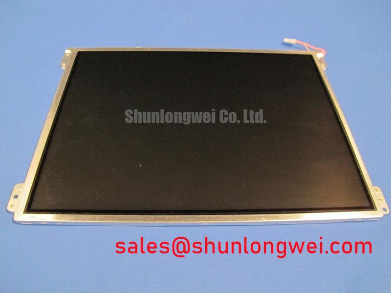
Begin incoming inspection by placing the LTM10C321N on an ESD-safe bench, checking the display face, perimeter seal area, rear housing, connector body, and flex interface for handling damage before electrical connection. This product is listed as an LCD/HMI panel in a TFT-LCD display module enclosure from Toshiba / Samsung in the supplied record; the record confirms its factory specification status but does not provide verified electrical, optical, interface, dimensional, or environmental rating values. System integrators should verify these requirements from the original panel documentation and the host equipment service record before replacement or new integration.
| Product Attribute | Verified Product Information |
|---|---|
| Model | LTM10C321N |
| Manufacturer | Toshiba / Samsung as listed in the supplied record |
| Product Category | LCD/HMI Panel |
| Module Type | TFT-LCD Display Module |
| Specification Status | Factory specification status noted; key values not provided |
For repair work, compare the original panel label, connector orientation, mounting interface, controller-board interface, and display image behavior before installation. A panel with the same model designation still requires a complete host-side compatibility check covering display timing, signal mapping, backlight drive arrangement, supply sequencing, mechanical stack-up, and touch-overlay clearance where applicable.
During receiving inspection of an LTM10C321N module, illuminate the complete screen with controlled full-white, mid-gray, and black image patterns. This process helps reveal visible non-uniformity, edge discoloration, pressure marks, intermittent line artifacts, and isolated pixel abnormalities before the unit is installed behind a bezel. Record observations under consistent ambient lighting rather than judging brightness from a powered-up desktop image alone.
Thermal cycling can affect an LCD assembly through changes in liquid-crystal response, optical-layer adhesion behavior, perimeter sealing condition, cable stiffness, and chassis stress. The supplied factory information does not confirm an operating range from −30°C to +85°C for this specific model. That range should therefore be treated only as an environmental evaluation condition for the host equipment, not as an official LTM10C321N rating. When a display is expected to operate in cold surroundings, designers should verify the permitted panel operating temperature, storage temperature, image-response specifications, and any approved warming strategy in original documentation.
At sub-zero ambient temperature, liquid-crystal response can become visibly slower. Gray transitions may appear delayed, and moving graphics can look smeared even where the signal path is electrically correct. This is a general display behavior and not a fault diagnosis specific to the LTM10C321N. A controlled check should compare the panel at normal room conditions and at the actual equipment environment while using the same timing source, brightness control state, and test pattern. If a heater strip or enclosure warming arrangement exists in the host design, its control behavior should be verified against the original equipment requirements rather than adjusted by assumption.
Inspect the visible perimeter of the panel for uneven compression, separation, residue, or localized light leakage after thermal exposure. Such observations can indicate that the display stack-up, bezel contact points, gasket loading, or enclosure geometry requires further review. For long-term service planning, engineers can refer to Industrial Display & HMI Solutions for broader integration considerations involving enclosure protection, viewing conditions, maintenance access, and environmental evaluation.
Display Data Mapping Alignment & Even/Odd Channel Signal Integrity
Before connecting the LTM10C321N to a controller, inspect the mating connector under magnification and confirm that the cable latch, keying features, conductor alignment, and strain-relief path match the original assembly. A display can show split images, incorrect colors, missing image sections, intermittent vertical content, or unstable synchronization when a cable is incompletely seated or when the controller output does not match the panel’s documented mapping.
The supplied factory record identifies the product category and TFT-LCD module format, but it does not confirm the required logic supply, interface standard, pin count, clock frequency, VESA mapping, JEIDA mapping, or power-on timing requirements. The system integrator should verify the required supply voltage from the original panel documentation. It is not appropriate to assume a 3.3V or 5.0V logic rail, LVDS configuration, or a particular mapping format solely from the model category.
VESA and JEIDA conventions can represent color data differently, so mapping alignment needs confirmation at the display-controller level. If the host system produces unusual color ordering, tonal distortion, or repeated image regions after a replacement, inspect the transmitter configuration and compare it with the known working controller setup. Even and odd channel continuity also deserves attention where the documented interface uses multiple differential data paths. A continuity check with power removed can help identify cable damage, while oscilloscope-based comparison against a known-good signal path may help distinguish timing or signal-integrity concerns from optical defects.
Differential-routing quality is a Design Consideration rather than an official panel specification stated here. Controlled impedance, matched path geometry, uninterrupted return paths, and connector grounding practices can reduce susceptibility to data corruption in a high-speed display link. The actual impedance target, clock tolerance, data hold requirement, and permitted power-rise interval must be taken from the panel documentation and validated in the finished equipment. Do not modify transmitter settings or supply sequencing based on a visual symptom alone.
💡 Bench Tip: Disconnect system power and use ESD controls before reseating the display cable, then insert the flex or harness evenly so the connector locks without side-loading the contact area.
Grayscale Inversion Mitigation & Viewing Direction Alignment
Use a full-screen grayscale ramp and a slow moving gray test pattern to assess the optical behavior of an installed LTM10C321N. Observe from the operator’s intended eye position first, then from above, below, and each side. This is especially important where a replacement panel is used in an existing industrial HMI, navigation terminal, monitoring station, or service console whose bezel angle was designed around the original display orientation.
The available official product information does not confirm whether the LTM10C321N uses a normally white TN architecture, IPS technology, MVA technology, anti-glare treatment, a specified viewing direction, or a stated viewing-angle rating. Terms such as 85°/85°/85°/85° must not be applied to this model without the original manufacturer documentation. Viewing-angle behavior should instead be evaluated directly on the actual panel and compared with the outgoing unit or approved equipment specification.
Grayscale inversion, apparent contrast change, and color shift can be associated with panel technology, viewing direction, optical films, controller output configuration, and ambient reflections. They should not be attributed to one cause without inspection. When a display appears correct at the center but changes substantially when viewed from the expected operator position, verify panel orientation, mounting angle, display-controller settings, and the original unit’s mechanical reference. A camera image alone is often insufficient because camera exposure and white balance can mask what an operator sees.
High ambient illumination can also alter perceived contrast. A front cover lens, protective overlay, or anti-reflective treatment in the host equipment may contribute more to outdoor readability than the bare LCD surface itself. For potential use in equipment such as a marine radar or navigation bridge console, the panel should be considered only after enclosure sealing, viewing position, sunlight exposure, display-controller compatibility, and service access have been verified. This is a compatibility evaluation example, not a declared application rating for the LTM10C321N.
Where image flicker, occasional pixel instability, or unstable grayscale appears during temperature changes, inspect the host timing source and data connection before assuming that the LCD cell is responsible. Clock jitter, insufficient data timing margin, connector oxidation, cable movement, and supply disturbances can all affect the displayed image. General insulation and spacing practices within surrounding powered equipment may also be reviewed under the principles described in Insulation Coordination, while keeping such system-level evaluation separate from unverified panel ratings.
Industrial Bezel Mechanical Envelope Tolerances & Mounting Screw Torque Optimization
Check the LTM10C321N against the original mechanical envelope before fastening it into an industrial bezel. Confirm the outer dimensions, active-area alignment, mounting-hole location, connector clearance, rear-depth allowance, cable bend path, and clearance to any touch panel or protective window from the original panel drawing. The supplied product information does not include verified dimensions or mounting-hole specifications, so these values must not be inferred from nominal display size or from another TFT module.
Mechanical loading can create optical defects that are easily mistaken for panel failure. Localized compression near an edge or mounting point can appear as bright pressure zones, dark-field mura, temporary color change, or visible distortion when the screen is powered. A practical check is to inspect the panel before fastening, after light hand placement in the bezel, and after final assembly using the same black, white, and gray images. If a pattern changes as the bezel is tightened, review contact surfaces, spacer placement, gasket thickness, fastener sequence, and chassis flatness.
The suggested 0.35–0.45 N·m M3 torque range is not confirmed as an official LTM10C321N mounting requirement and must be treated as a General Industry Design Consideration only. Final mounting torque depends on the panel drawing, screw engagement, bezel material, thread construction, spacer design, and permitted mechanical load. Use the torque and tightening method defined by the original equipment manufacturer or the panel’s official mechanical specification.
A cross-pattern tightening sequence can help distribute bezel loading where multiple fasteners are used, but it does not replace dimensional control. Designers should ensure that the panel is supported by intended mounting features rather than by uncontrolled contact against the display face, connector, or edge structure. After installation, recheck connector retention and inspect the image at low and high brightness settings. If optical non-uniformity appears only after final assembly, relieve the mechanical load and investigate the enclosure fit before changing electrical settings.
For equipment exposed to vibration, salt-laden air, or repeated service access, cable retention and enclosure integrity should be evaluated as host-system concerns. Do not assume that the LTM10C321N alone provides corrosion resistance, vibration certification, ingress protection, EMC compliance, insulation reliability, or a defined operating lifetime unless those claims are confirmed in the applicable original documentation.