

Content last revised on October 5, 2026
Single Vertical Hairline Defects and Column Fault Localization
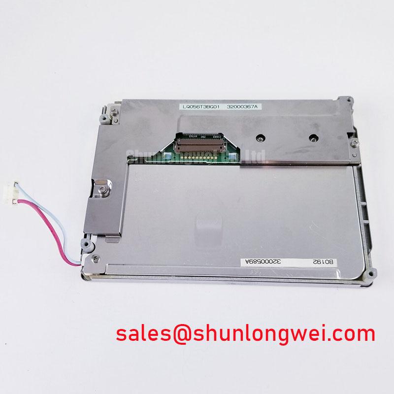
Inspect the LQ056T3BG01 label and connector area before powering the panel, then photograph the unlit screen under oblique light so surface marks can be distinguished from defects visible only during operation. Sharp identifies this part as a TFT LCD display module in the industrial LCD and HMI panel category (Official Factory Specification). The supplied factory specification does not establish its resolution, dimensions, electrical interface, supply voltage, backlight type or optical ratings; confirm those details against the original panel documentation before connecting a test fixture.
Begin an incoming inspection with separate full-screen red, green and blue images, followed by white, black and neutral gray. This sequence helps reveal a narrow vertical line that blends into a detailed HMI image. Record whether the line stays at the same column, changes with the displayed color, or appears only at particular gray levels. A fixed line can narrow the investigation, but it does not by itself identify a failed column driver: source timing, connector contact and the panel assembly remain possible contributors.
With the image still displayed, view the suspect region from an angle while directing a flashlight obliquely across the screen. Compare the line with its appearance when the panel is unpowered. A mark visible on the unlit surface calls for a different inspection than a line present only in the driven image. Uneven illumination may also resemble a display fault, so repeat the comparison on a uniform white image and record any change with brightness. Do not infer an internal fracture from the line alone.
For a replacement assessment, keep the source equipment, image pattern and camera exposure consistent when comparing panels. Note the position and width of any defect rather than recording only “line present.” If another panel is being evaluated, including LM64P10, treat it as a separate part requiring confirmation of mechanical fit, interface, power requirements and optical performance; a similar repair context does not establish interchangeability.
Edge Illumination, Brightness Uniformity and Thermal Fit
Display a full-white image after the panel has reached a stable operating condition. Examine the edges for bright bands, dark corners and color shifts, then compare the center with the perimeter using the same viewing angle. A visible gradient is a reason to inspect the optical stack, drive conditions and surrounding enclosure—not proof of a particular light-guide material or light-source failure. The supplied factory specification does not identify the LQ056T3BG01 backlight technology, brightness, color temperature or rated life, so no lifetime or luminance target should be assigned to this module from appearance alone.
Design Consideration: if the original equipment uses an edge-mounted light source, its mounting and thermal path should avoid concentrated heating near the visible area. Inspect the equipment’s existing supports and ventilation before changing them; an added rail or pad can introduce pressure as well as conduct heat. Check brightness and color uniformity again after the panel is installed in its final enclosure, because bezel pressure and nearby heat sources can change what is seen on an open bench.
For dimming complaints, verify the equipment’s backlight-control method from its schematic and observe the light output at the settings where the complaint occurs. A current-regulated driver or pulse-width modulation scheme must not be assumed from the panel model alone. If visible flicker or camera banding appears, compare the control waveform and light output under the actual operating conditions rather than prescribing a frequency without the original design limits. Broader enclosure and environmental considerations are discussed in Industrial Display & HMI Solutions.
Display Interface Synchronization and Supply Verification
Before attaching a signal generator, match the connector orientation and pin assignment to the original LQ056T3BG01 documentation. The supplied factory specification does not confirm a TTL RGB or LVDS interface, a logic supply voltage, data mapping or power-on sequence. Applying a familiar display-cable pinout without that confirmation is not a valid compatibility test. Check the host board and panel documentation together, including the return paths and any separate illumination connection.
Once the documented interface is established, use a current-limited bench setup appropriate to that documentation and observe the supply at the panel connector during startup. Compare clock and data activity with a known-good signal path where available. Split images, unstable colors or intermittent startup can involve timing, signal integrity, supply behavior or contact resistance; none is a unique diagnosis. The system integrator should determine acceptable rise times, routing impedance and timing margins from the specified interface and validate them on the assembled equipment.
💡 Bench Tip: Disconnect power and use ESD protection before reseating the display cable, then check that it enters the connector evenly and that its lock closes without forcing the cable. After reseating, repeat the same test image and gently inspect the cable’s supported routing. A symptom that changes with cable position warrants investigation of the connector and flex path, without assuming that the panel itself is defective.
Polarizer Inspection under Direct Industrial Lighting
Inspect the powered screen from the viewing positions used in the equipment, first under diffuse light and then under its normal overhead lighting. Watch for glare that obscures dark details, apparent grayscale reversal at an angle, and discoloration that moves with viewing position. These observations help define the optical fit of the installed assembly, but they do not establish that LQ056T3BG01 uses TN, IPS or MVA technology. Its viewing-angle limits, anti-glare treatment and contrast rating must come from the original panel documentation before they are used as acceptance criteria.
Use the unpowered inspection to map scratches, pressure marks and coating irregularities; use uniform gray and color images to see whether a reported blemish remains in the same place when the displayed content changes. Avoid pressing on the viewing surface during this check. Design Consideration: enclosure supports should retain the module without imposing localized stress on the visible area, particularly when the finished equipment will experience vibration or temperature changes. Confirm the resulting image in the assembled unit rather than relying solely on an open-panel bench result.
A surgical navigation or ultrasound diagnostic display is a possible compatibility-evaluation context, not a certified application or established fit for this part. Before approving a repair in such equipment, compare the original panel records with the candidate module’s connector, electrical limits, active area, optical behavior and mounting features. If a stationary interface has left a persistent visible pattern, document its appearance on neutral test images and assess the equipment’s display-use practices separately; that observation alone does not establish the panel’s remaining service life.