
1 Introduction
In recent years, with the development of technology, the technology of thin film transistor (TFT) has been continuously developed and optimized, and the thin film transistor liquid crystal display (TFT-LCD) has quickly become the mainstream display screen in the market. However, TFT-LCD displays still have many problems, such as screen flicker which can cause eye discomfort.
The panel will switch between positive and negative frame polarity during display. When the brightness of the positive frame and the negative frame are inconsistent, the positive and negative frame switching will cause the product image quality to appear alternately bright and dark and the screen flickers. Especially at low frequencies, the flicker problem will be more serious due to the reduced refresh frequency of the product, and it is very important to improve the display quality of the product. Previous researchers have analyzed and studied the flicker performance of electrical angles such as Kickback Voltage and leakage current. Lin Hongtao et al. not only focused on the basic leakage and other factors to analyze Flicker, but also paid attention to the drift phenomenon of Flicker. Xu Liyan et al. explained the factors of Flicker drift from the direction of the increase of liquid crystal ions caused by illumination. Yan Liang et al. demonstrated the influence of various drive methods on flicker from the perspective of panel drive architecture. According to previous research , if the size of the two pixels is inconsistent, and the common voltage (VCOM) matching difference is large in the design, it will cause the display difference of the screen flicker. Li Xin et al. from the perspective of TFT device technology, through adjusting the process parameters to affect the device characteristics and capabilities, so as to carry out a correlation study on thin film transistor liquid crystal display (TFT-LCD) Flicker capabilities. Zhang Hanmin's research carried out the research and development of automatic correction of display flicker from the perspective of automatic voltage adjustment.
This article mainly studies the Flicker performance of LCD products from the perspective of liquid crystal materials. Through the optical simulation test of different parameters of the liquid crystal, the optical mode under the interaction of the liquid crystal and the electric field under Flicker is studied and analyzed, so as to finally converge the performance related factors. This has certain guiding significance for the improvement of product performance, and at the same time provides new ideas for the research of LCD Flicker performance, and lays a good foundation for improving the picture quality of the product under the display and even the low-frequency refresh frequency.
2 Simulation design analysis
The pixel electrode width-to-length ratio (ITO W/L) design scheme adopted by the panel is determined based on design perspectives such as transmittance and contrast. At this stage, the market has certain requirements for the quality of image flicker at low frequencies. New requirements are put forward for the W/L of ITO, and the influence of liquid crystal is also considered simultaneously.
2.1 Different W/L ITO design evaluation simulation
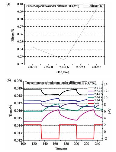
Through different ITO W/L designs, combined with the flexural electrical effect of liquid crystals, the Flicker performance is simulated and evaluated. The simulation results are shown in Figure 1. With the change of ITO W/L, Flicker exhibits optical performance that first decreases and then increases. Through the simulation waveforms of transmittance under different W/L, it can be seen that as the positive and negative frame voltages change, the LC is constantly flipping, resulting The fluctuation of the transmittance, and then the screen flicker, and as the W/L gets closer and closer to 1, the risk of flicker caused by the liquid crystal deflection effect is also minimized.
2.2 Simulation of different liquid crystal response time
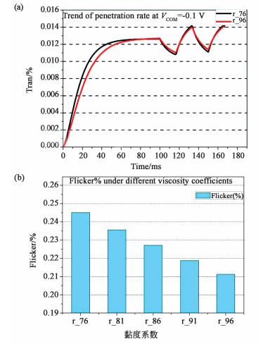
By analyzing the gradient change of the liquid crystal rotation viscosity, the simulation confirms that the Flicker situation is shown in Figure 2. Figure 2(a) is the simulation result of the transmittance change with time when the VCOM bias voltage is -0.1 V under different liquid crystal viscosity. It can be seen from the analysis in the figure that when the VCOM bias is -0.1 V, the rotation time of the liquid crystal with high viscosity coefficient is lengthened, which will result in a decrease in the range of transmittance change within one frame. Therefore, from the point of view of image quality performance, Flicker has better performance. It can be seen from Figure 2(b) that the larger the viscosity coefficient, the better the simulated Flicker performance.
3 Actual product confirmation and discussion analysis
3.1 Flicker performance under different liquid crystal parameter viscosities
3.1.1 Flicker brightness test
Figure 3(a) is the brightness test spectrum of the Flicker screen of the panel, which mainly shows the results of the brightness changes over time under different VCOMs. Combining the two spectral curves when VCOM is -0.29 V and -0.25 V, it can be seen that the brightness of the upper flat area at VCOM=-0.29 V is significantly higher than the result at VCOM=-0.25 V. From this, it can be inferred that the upper flat area of brightness is the positive frame of light emission, and the lower flat area of the brightness is the negative frame of light. The research of She Xiaofei and others showed that the dominant ions in the LCD screen are negative ions, and the light-emitting areas of the positive and negative frames are the pixel electrode space (ITO Space) and the pixel electrode (ITO Slit) respectively. Therefore, it can be concluded that, as shown in Figure 3(b) and (c), in the normal frame, the ions in the box are mainly distributed in the pixel electrode area, and the pixel electrode area is smaller than the pixel electrode gap area, which is correct for the frame brightness. The impact of the change is small, resulting in a better ability to maintain the brightness of the positive frame; while in the negative frame, the ions in the box are mainly distributed in the pixel electrode gap area, and the pixel electrode gap area is relatively large, which has a large impact on the brightness change of the negative frame, resulting in negative The frame brightness maintenance ability is poor.
3.1.2 Theoretical analysis of product testing
Combined with the change in the response time of the liquid crystal, from the perspective of brightness fluctuation, a liquid crystal with a low response time will cause the panel to reduce the brightness change under the same VCOM bias. Reflected in the depth performance of Flicker, when the panel is matched with a low response time liquid crystal, the brightness change amplitude is smaller, and the Flicker span is larger.
3.2 Product Flicker performance test
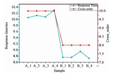
Figure 5 shows the test data of Flicker span (Spec <-30 dB) and response time of liquid crystals with different response times. From the test data, as the response time of the test sample increases, the Flicker jumper of the product increases significantly, which is consistent with the simulation conclusion. This is mainly because the longer the response time of the liquid crystal on which the product rides, and under the same VCOM bias, the smaller the brightness change range of the product, the larger the Flicker step.
4 Conclusion
Through the product brightness capability test under different VCOM on the TFT-LCD panel, it is confirmed that in the different areas of the pixel electrode, because of the difference in the light-emitting area and the existence of the ion movement concentration effect, the brightness maintenance ability of the flat area under the negative frame brightness is confirmed A phenomenon in which the brightness maintenance ability of the flat area under poor and normal frame brightness is better. At the same time, based on the Flicker capability test results of the product under different response times, by comparing the difference optimization of the liquid crystal response time, the optimization of the Flicker capability from the 8th to the 10th order is realized. Finally, combined with simulation verification, the liquid crystal response time factor of the relevant Flicker performance is converged, and the liquid crystal light-emitting behavior theory of panel flicker is established. This will help the improvement of the product display capability and provide a reference for the development direction of subsequent products.