
Content last revised on September 10, 2026
Sharp LM64P10 FSTN LCD Display for Industrial Control Panels
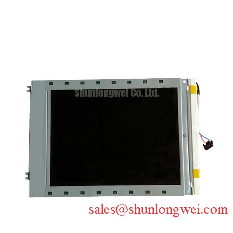
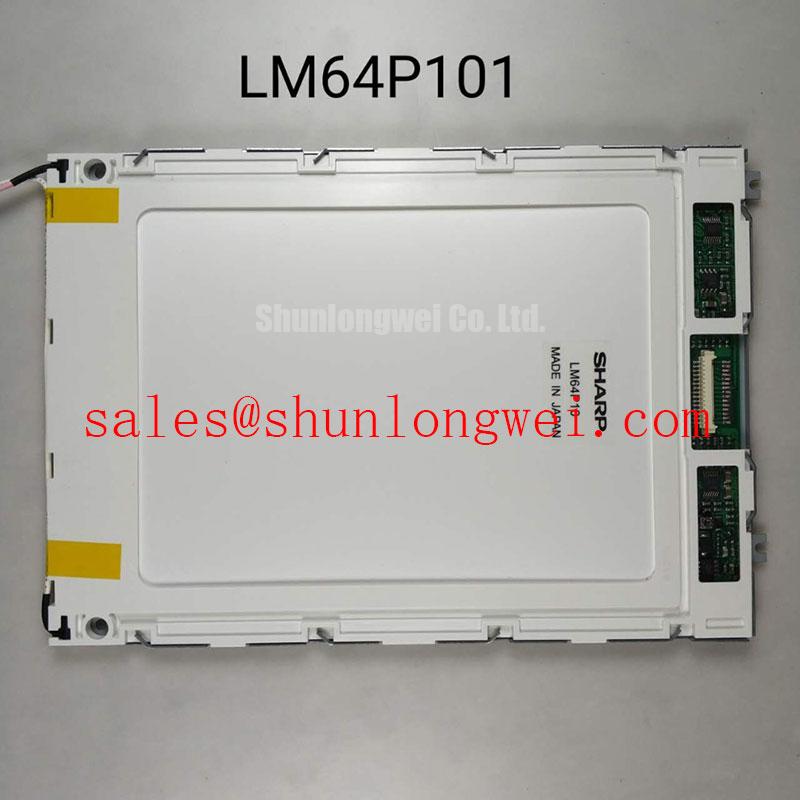
Begin incoming inspection by checking the Sharp LM64P10 label, examining the panel and connector area for physical damage, and confirming the required electrical limits against the original equipment documentation before applying power. This panel is specified as a 9.4-inch-class FSTN monochrome LCD display with a 640 × 480 VGA resolution, making it relevant to legacy operator interfaces, protection terminals, and control consoles that require a clear black-and-white display.
The published product information identifies the interface as 4-bit parallel data. This point is important during replacement work because the available information does not identify the LM64P10 as a native LVDS panel. A system integrator should therefore verify the host controller, pin assignment, logic levels, enable timing, and any required interface board from the original display assembly before selecting a cable or converter.
| Parameter | Specified Value | Engineering Significance |
|---|---|---|
| Manufacturer | Sharp | Use the original equipment documentation to confirm mechanical and electrical interchangeability. |
| Display type | FSTN monochrome LCD | Provides a high-contrast black-and-white image for text, alarms, measurements, and status information. |
| Resolution | 640 × 480 pixels, VGA | Supports legacy industrial software and controllers using VGA-class screen formatting. |
| Active area | 147.18 × 110.38 mm | Defines the visible image area and helps technicians compare the replacement with the installed panel. |
| Interface | 4-bit parallel data | Requires a compatible controller or interface arrangement; do not assume LVDS compatibility. |
| Backlight | CCFL | Requires verification of the original high-voltage backlight inverter and lamp connection. |
| Typical contrast ratio | 18:1 | Supports clear separation between character segments and the background under suitable viewing conditions. |
| Operating temperature | 0°C to 45°C | Indicates use in controlled indoor or industrial environments within the stated range. |
The active area of 147.18 × 110.38 mm should be checked against the old panel before installation. A matching diagonal description alone is not sufficient: bezel clearance, screw positions, connector orientation, cable reach, and the optical position of the image window can all affect whether a replacement is mechanically usable. The LM64P10 should be evaluated as a complete panel replacement rather than as a universal substitute for every VGA-format display.
For equipment procurement, the inspection record should include the model marking, visible glass condition, connector condition, active-area measurement, and a powered image test. Because this product uses a CCFL backlight, the replacement procedure should also identify the inverter fitted in the host equipment. The panel data supplied here does not establish an inverter input voltage, lamp current, lamp length, connector pinout, or insulation rating, so these values must be taken from the original Sharp documentation or the equipment service manual.
Parallel Interface Timing and Differential LVDS Compatibility Checks
Connector count should not be used as an interface diagnosis. A 20-pin or 30-pin cable may appear in many display assemblies, but the available specification for the LM64P10 identifies 4-bit parallel data, not a differential LVDS interface. Before connecting a replacement, trace the host-board wiring and inspect signal labels with the equipment powered down, compare the connector keying and pin labels, and consult the original panel drawing. Applying an LVDS transmitter to a parallel-data panel can produce a blank display or electrical stress, while using a parallel controller on an LVDS assembly can create a completely different failure pattern.
Timing verification remains useful when the host controller communicates with the panel through a parallel bus. Check the controller’s data setup and hold behavior, display enable sequence, clock polarity, and reset behavior against the source equipment documentation. The panel specification provided here does not state a pixel clock limit, data setup time, data hold time, power-on delay, logic supply voltage, or allowable rise time. These should not be inferred from the VGA resolution.
The same caution applies to the commonly discussed 100-ohm differential routing practice. That is a Design Consideration for differential transmission lines, not an official LM64P10 parameter. It should only be applied when the actual system topology contains differential pairs. For a confirmed differential interface, designers should control pair geometry, reference-plane continuity, return-current paths, and connector transitions, then verify eye quality and clock margin at the receiver. Those checks do not replace confirmation of the LM64P10’s documented parallel interface.
Image splitting, unstable characters, or repeated rows should be investigated by comparing the suspected panel path with a known-good controller and by observing the data and control signals with suitable test equipment. Such symptoms may involve pin mapping, timing polarity, cable seating, controller configuration, or a host-board fault. They should not be assigned to pixel-clock skew without measurement.
Backlight control also requires separation between confirmed data and system-level assumptions. The LM64P10 is specified with a CCFL backlight; the supplied information does not confirm PWM dimming, a brightness-control input, or compatibility with an LED constant-current driver. If a retrofit is being considered, the system integrator should verify optical output, inverter behavior, insulation, electromagnetic emissions, connector voltage, and mechanical fit as a complete assembly.
Where a different display architecture is under evaluation, the LMS700KF01-001 can be reviewed as a separate same-size-class and resolution-oriented option. It should be compared through its own datasheet rather than treated as an automatic substitute for the LM64P10.
FSTN Grayscale Inversion Mitigation and Viewing Direction
FSTN monochrome technology should be assessed by viewing the actual characters and graphics from the operator’s normal position. The published specification confirms the display type and a typical contrast ratio of 18:1, but it does not provide viewing-angle figures, a formal grayscale-inversion limit, surface treatment data, or a luminance distribution map. Incoming QA should therefore examine dark characters, fine lines, alarm symbols, and large filled areas from the intended horizontal and vertical viewing positions.
Monochrome panels can show a change in apparent contrast when the viewing direction moves away from the preferred axis. This is a Design Consideration for the enclosure and mounting bracket, not a stated LM64P10 viewing-angle specification. If the panel is installed in a high-voltage substation protection or SCADA dispatch console, position the screen so operators can read alarm text without repeatedly tilting the panel or relying on reflections from nearby lamps.
Surface glare should be judged with the final bezel, window, and room lighting in place. The available information does not confirm an anti-glare etch, anti-reflection coating, haze value, or transmittance. Do not describe the LM64P10 as AG or AR treated unless the original panel documentation confirms it. If a protective front window is used, assess reflected light, contrast loss, viewing angle, and cleaning compatibility after assembly.
The T-CON or controller board should be evaluated through the image it produces rather than by assuming a particular gamma architecture. The supplied product data does not specify grayscale-voltage values, gamma correction points, frame timing, or internal controller topology. When characters appear too light, too dark, or uneven across the screen, compare the controller output, bias conditions, cable contact, and display settings with a known-good unit. A panel-level conclusion should only be made after the host electronics have been checked.
Industrial touch operation is not identified in the LM64P10 specification. If the host equipment places a resistive or capacitive touch overlay over the LCD, the integrator should test glove operation, wet-finger response, calibration, bezel pressure, and electromagnetic interference as properties of the complete touch assembly. Those characteristics cannot be assigned to the LCD panel itself.
💡 Bench Tip: Use ESD protection and insert the flat cable squarely with its contacts fully aligned before locking the connector.
Optical Luminance Degradation and CCFL-to-LED Modernization Pathways
The LM64P10 is documented with a CCFL backlight, so a powered inspection should include ignition behavior, visible uniformity, flicker, abnormal noise, and stability after warm-up. The supplied specifications do not provide lamp voltage, lamp current, starting voltage, brightness, luminance uniformity, half-life, or inverter compatibility. These omissions matter when a field engineer is diagnosing a dim image: the panel, lamp, inverter, cable, and controller must be evaluated as separate parts of the lighting path.
CCFL systems use a high-voltage inverter, but the exact cold-start voltage and operating conditions are system-dependent and are not official LM64P10 values in the supplied data. Technicians should use the original inverter documentation and appropriate high-voltage measurement methods. Visual inspection alone cannot establish whether a lamp is electrically open, whether the inverter is entering protection, or whether the LCD image itself has lost contrast.
An LED modernization project is a system redesign, not a direct assumption about this panel. The integrator should verify the optical stack, lamp position, illumination uniformity, thermal conditions, driver current regulation, dimming interface, connector insulation, and electromagnetic compatibility. A constant-current LED driver may be appropriate for a separately validated retrofit, but the LM64P10 specification supplied here does not confirm an LED input or an internal LED backlight.
Backlight fault diagnosis should begin with power removed and the inverter and lamp connectors visually inspected. During controlled testing, technicians can compare the inverter enable signal, supply behavior, protection response, and illumination against a known-good assembly. An open or short indication from an inverter does not by itself prove that the LCD panel is defective, because cable seating, inverter protection, lamp aging, and host control signals can produce related symptoms.
For a related display topology, the LM057QC1T08 may be reviewed as a separate product reference for driver and display-system evaluation. Its interface and backlight requirements must be checked independently. Long-term integration practices can also be compared with the Industrial Display & HMI Solutions engineering reference, while avoiding assumptions that its system guidance changes the LM64P10’s published ratings.
Preventing Frame Lag and Image Smearing in Cold or Outdoor Installations
The specified operating temperature for the LM64P10 is 0°C to 45°C. This boundary should be treated as an official operating specification for the panel information provided, not as evidence of suitability for cryogenic storage or outdoor sub-zero service. Liquid-crystal response can change with temperature, and image transitions may appear slower when the panel is operated outside its specified range. The provided data does not state gray-to-gray response time, storage temperature, thermal cycling capability, sealant performance, or cold-start behavior.
For a substation protection or SCADA console, the enclosure designer should first confirm the actual temperature at the LCD surface rather than relying only on the room or cabinet rating. Heating, ventilation, condensation control, solar loading, and the position of nearby power electronics can affect the panel environment. If the measured condition approaches or exceeds the specified range, system engineers should validate readability, start-up behavior, contrast, and image stability during controlled environmental testing.
Frame lag or smearing should be investigated by displaying repeatable text and moving test patterns while recording the panel temperature and controller timing. Compare the result with a known-good panel on the same host board. Potential contributors include operating temperature, controller refresh configuration, cable integrity, bias conditions, and the source image itself. A visual symptom should not be assigned to liquid-crystal viscosity without checking these interacting factors.
Outdoor visibility also depends on the enclosure window, ambient illumination, viewing direction, and any installed optical overlay. The LM64P10 data confirms FSTN monochrome operation and a typical 18:1 contrast ratio, but it does not specify sunlight readability, anti-glare treatment, anti-reflection performance, or luminance reserve. Designers should test the complete assembly under the intended lighting and verify that alarm characters remain distinguishable without introducing excessive reflections.
When the replacement is installed, route the cable so it is not sharply folded or placed against a moving bezel, secure the panel without uneven mechanical loading, and repeat the full-screen test after final tightening. Check black, white, and intermediate display patterns for missing segments, unstable areas, uneven illumination, and intermittent connector behavior before returning the industrial console to service.