

Content last revised on September 13, 2026
Full-Screen Primary Color Screening: Stuck Sub-Pixels and Background Uniformity Audit
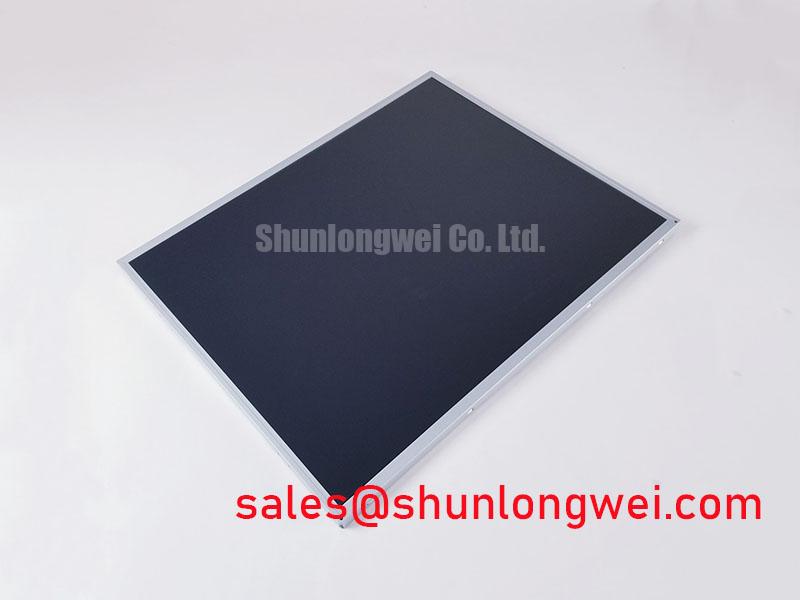
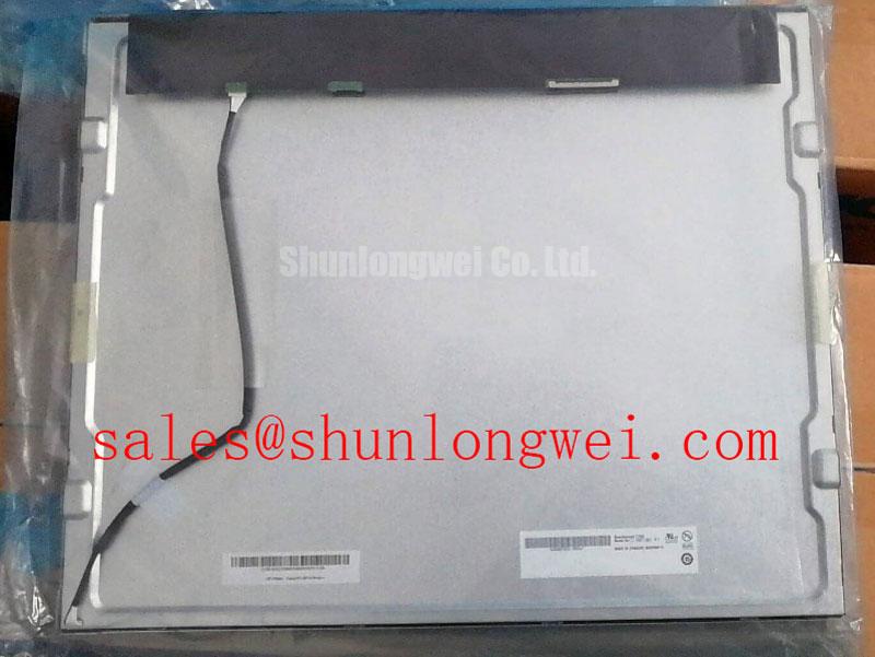
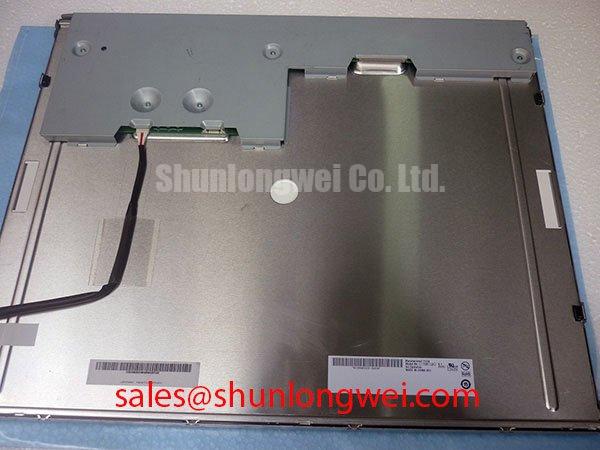
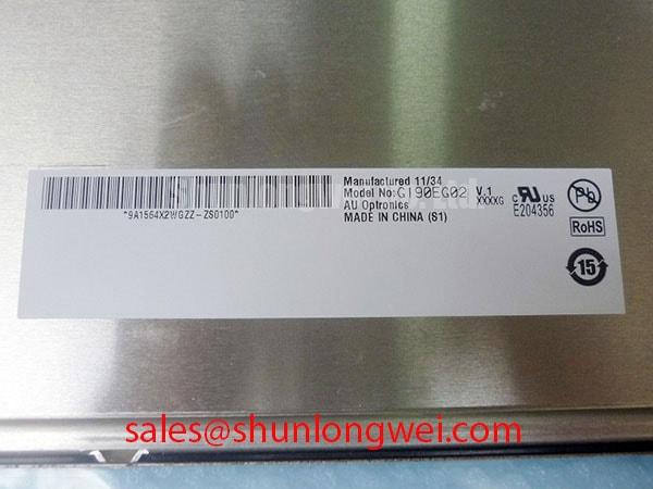
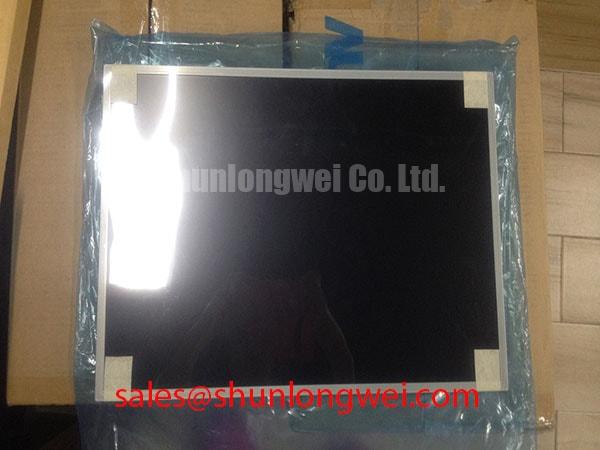
Begin a replacement inspection by comparing the panel label with G190EG02 V1, then check the connector, mounting points, bezel condition, and visible screen area before applying power. AUO identifies this unit as an Industrial Grade LCD/HMI Panel supplied as a TFT-LCD Display Module. The available factory information confirms the model and product category, while interface pinout, resolution, luminance, dimensions, backlight type, and operating limits should be verified against the original panel documentation before installation.
For a used CNC operator panel or robot teach pendant, perform a controlled display check with full-screen black, white, red, green, and blue images. Observe the panel from a normal viewing position and then inspect suspected areas with a flashlight held at approximately 45 degrees. This dark-shadow method can help distinguish a backlight or optical non-uniformity from a localized pixel or bonding-line defect, but it is a screening technique rather than a factory acceptance test.
Record whether an artifact remains fixed when the displayed image changes. A fixed bright point, dark point, or narrow line should be compared with the same area on a known-good signal path. If the panel uses a high-speed serial interface, the system integrator should verify the original transmitter type, cable construction, termination, differential impedance, and pair-to-pair skew from the panel and controller documentation. Do not impose a generic interface value on this model without confirming its actual electrical architecture.
During the inspection, also inspect the front polarizer, edge seal, connector lock, and flex-cable transition for contamination or mechanical marks. These observations are useful when deciding whether a display fault follows the panel, the cable, or the controller board.
Optical Luminance Degradation Curve and Backlight Retrofit Pathways
The backlight technology for G190EG02 V1 must be confirmed from the original AUO documentation or the installed assembly before any retrofit decision. A replacement driver designed for one backlight type should not be connected to another type based only on connector similarity. The system integrator should verify the required supply, enable signal, dimming method, current regulation, and protection behavior from the original panel documentation.
For a field assessment, measure brightness at consistent screen settings and ambient conditions, then compare the result across the center and edges of the active area. A gradual reduction may involve the backlight assembly, optical stack, driver output, or thermal environment. Acoustic noise, intermittent ignition, visible flicker, or unstable brightness should be investigated at the driver and cable level rather than assigned to the LCD glass without measurement.
If an LED modernization is being considered for equipment such as a CNC operator panel or robot teach pendant, designers should verify optical compatibility, driver control logic, heat dissipation, enclosure clearance, and dimming behavior. The linked LM190E08-TLG6 may be reviewed as a related display solution, but compatibility with this AUO module remains system-dependent.
Industrial Bezel Mechanical Envelope Tolerances and Mounting Stress Control
Before fitting the panel into a machine bezel, compare the replacement assembly with the removed unit using the original mounting drawing. Confirm the active-area position, connector exit direction, frame contact surfaces, screw locations, and clearance around the flex cable. The supplied information does not establish a dimensional drawing or approved fastener torque for this model, so the original AUO documentation and equipment chassis specification should control the installation.
Mechanical pressure can create localized optical non-uniformity, edge shading, or intermittent connector behavior. Install fasteners progressively and release any enclosure distortion before final tightening. A cross-pattern sequence is a reasonable Design Consideration for distributing mechanical load, but the correct torque must be determined by the chassis, insert, screw size, and panel construction rather than copied from a different display.
Inspect the dust gasket around the bezel for compression damage, gaps, and contamination. An incomplete seal can expose the display assembly to airborne particles and moisture, while excessive compression can transfer stress into the screen frame. Maintenance Note: Check the cabinet airflow path and bezel gasket condition during scheduled service, especially where temperature cycling can promote condensation.
For an alternative evaluation, engineers can compare the mechanical and electrical documentation for M185XW01 VE. It should be treated as a separate candidate requiring confirmation of dimensions, interface, optical performance, and enclosure fit rather than assumed to be a direct substitute.
TTL 24-Bit Digital RGB Bus Synchronization and Logic Power Rail Verification
The interface type and logic supply requirements for G190EG02 V1 are not included in the provided factory parameter set. The system integrator should verify whether the original equipment uses TTL RGB, LVDS, or another display link, together with the correct voltage, pixel mapping, clock polarity, enable timing, and connector pin assignment. Do not apply a 3.3 V or 5 V assumption without the original panel documentation.
When the screen shows split images, incorrect colors, missing columns, or unstable synchronization, first compare the controller output with the known-good signal path. Check connector orientation, cable seating, ground continuity, power-rail stability, display enable sequencing, and clock behavior under the actual enclosure temperature. If a serial link is used, route the signal according to the transmitter and receiver requirements, control return-current paths, and minimize noise coupling from motor drives and switching supplies.
Power sequencing should be verified with an oscilloscope against the panel documentation rather than inferred from a visually working display. Confirm that the logic rail reaches its specified operating range before enabling image data, and check shutdown behavior as well as startup. The Industrial Display & HMI Solutions reference can support broader enclosure, sealing, and environmental evaluation during equipment maintenance.
| Item | Confirmed information |
|---|---|
| Model | G190EG02 V1 |
| Manufacturer | AUO |
| Product category | Industrial Grade LCD/HMI Panel |
| Package or assembly type | TFT-LCD Display Module |
| Specification status | Model and product category confirmed; remaining specifications require verification against the original documentation |