
Content last revised on September 10, 2026
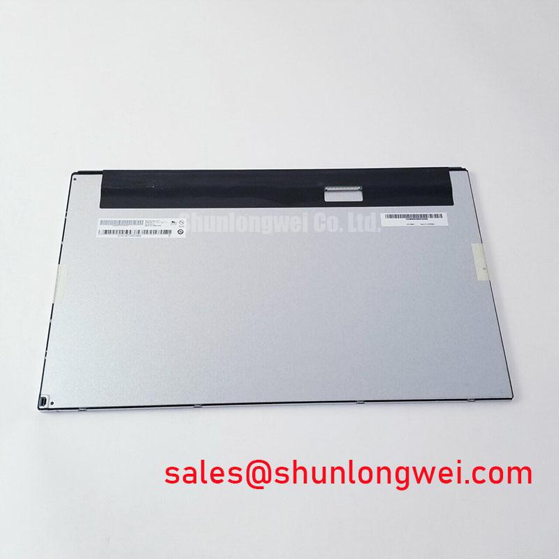
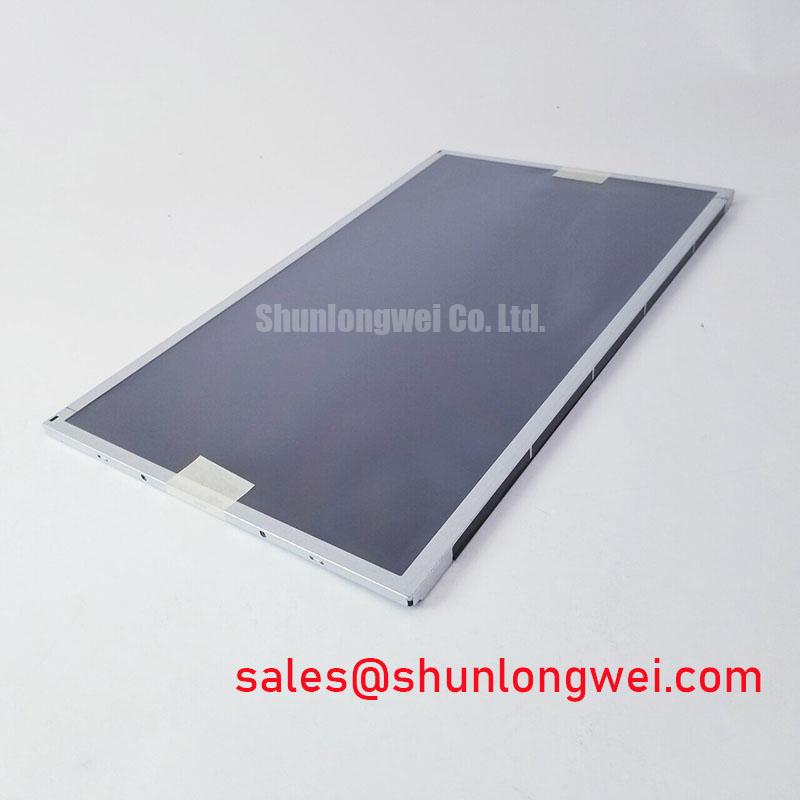
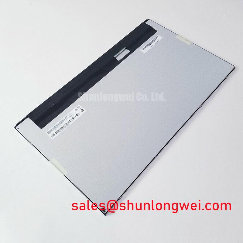
With the cabinet de energized, inspect the panel label, connector condition, bezel seating, and cable retention before fitting the M185XTN01.0 into an HMI assembly. This AUO unit is identified as an Industrial Grade LCD/HMI Panel in a TFT LCD Display Module format. For a repair decision, confirm that the original machine documentation matches the display interface, mechanical envelope, optical requirements, and power sequencing before connecting the replacement panel.
| Item | Reference Information |
|---|---|
| Model | M185XTN01.0 |
| Manufacturer | AUO |
| Product category | Industrial Grade LCD/HMI Panel |
| Display construction | TFT LCD Display Module |
| Specification status | Model identified; application details require matching documentation |
Viewing Technology and Viewing Angle Verification for Multi-Angle Consoles
Do not infer the viewing technology, viewing angle, surface treatment, or optical behavior of the M185XTN01.0 from the appearance of an installed panel. The available official product information identifies its industrial TFT LCD category but does not confirm a Super IPS or MVA mode, an 85 degree symmetric viewing cone, or an anti glare surface specification. For a multi angle control console, technicians should compare the original panel documentation and the actual installed viewing behavior before authorizing a replacement.
During a black screen complaint, separate image generation from illumination first. Power the host system, observe the panel under controlled light, and check whether a faint image remains visible. A faint image can point the investigation toward the backlight path, while a fully blank raster requires checks of host video output, connector engagement, panel supply, and initialization sequence. This is a diagnostic direction, not a single cause determination.
Display timing integrity is a Design Consideration. Clock stability, data hold timing, and transmitter behavior must be evaluated against the interface requirements documented for the original screen, especially when the equipment experiences changing ambient temperatures. When a same size reference is needed during an interface comparison, engineers can review the M185XW01 VE separately and verify every mechanical, electrical, and optical difference rather than treating it as a direct substitute.
Operating Temperature and Cold-Start Response Verification
The supplied factory information for M185XTN01.0 does not establish a specific operating temperature range, liquid crystal response time, perimeter seal construction, or backlight lifetime rating. It would therefore be inaccurate to assign a minus 30 degrees Celsius to plus 85 degrees Celsius rating, a gray to gray response result, or a brightness retention figure to this exact model without its matching AUO documentation.
For industrial HMI repair work, temperature is still an important Design Consideration. Slow image transitions after a cold start, delayed recovery after warm operation, dim output, or intermittent illumination should be recorded alongside enclosure temperature, supply behavior, and cable condition. These observations help distinguish a panel level concern from a host controller, power converter, or backlight driver issue. The system integrator should verify the required display supply voltage and backlight requirements from the original panel documentation.
For AGV and forklift telematics displays, vibration, enclosure sealing, thermal exposure, and available airflow are system conditions that require separate evaluation. Broader environmental integration practices can be reviewed in Industrial Display & HMI Solutions, while the final acceptance decision must remain tied to the original equipment requirements and tested panel behavior.
FFC/FPC Cable Shielding and Grounding Assessment
Horizontal noise bands, unstable pixels, intermittent color errors, or image flicker near variable frequency motor equipment should not be attributed to the LCD panel alone. Inspect the display cable for incomplete insertion, damaged locking features, sharp bend stress, contamination, and unsuitable routing beside high energy conductors. Check the host grounding arrangement and screen termination as defined by the equipment design.
Shield continuity and common mode noise control are Design Considerations, not verified product specifications of the M185XTN01.0. Where the original assembly uses shielded cable hardware, maintain the intended connector shell contact and cable routing method. If ferrite suppression is present in the original build, its location and type should be preserved until oscilloscope checks confirm the signal path is stable. Technicians should verify suspected interference against a known good cable path and host signal source.
⚠️ Field Alert: Disconnect system power and allow stored energy to discharge before removing or reseating any display connector.
Where a separate industrial display assembly is being assessed alongside the panel, the NL192108AC21 01 listing provides a neutral reference for reviewing another display solution; it does not establish connector or electrical compatibility with the M185XTN01.0.
LVDS Connector, Timing, Pixel Clock, and Skew Verification
Connector pin count, LVDS data mapping, logic voltage, differential impedance, pixel clock, and power on timing are not confirmed by the available official information for this model. A repair team must not assume a 20 pin or 30 pin connection, a 3.3 volt or 5.0 volt logic rail, or JEIDA or VESA mapping. These details must be read from the original panel datasheet, connector drawing, or qualified equipment documentation before installation.
Split images, shifted colors, repeated columns, or an illuminated panel with no usable picture can arise from several conditions, including an incorrect mapping, timing mismatch, cable fault, host board issue, or incomplete power sequence. Inspect the mating connector orientation, compare the original cable part marking where available, and measure host signals only with suitable test equipment and a verified reference path. The system engineer should validate peak timing and power sequence behavior during controlled switching tests.
Optical contrast under ambient light, sunlight readability, and anti glare performance also require model specific documentation or direct controlled evaluation. The M185XTN01.0 AUO industrial TFT LCD display module should be selected only after its confirmed interface and installation conditions match the equipment being repaired.