

Content last revised on September 10, 2026
Inspect the LJ640U30 Sharp Industrial LCD HMI Panel Before Integration
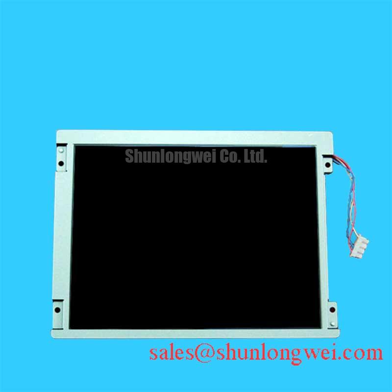
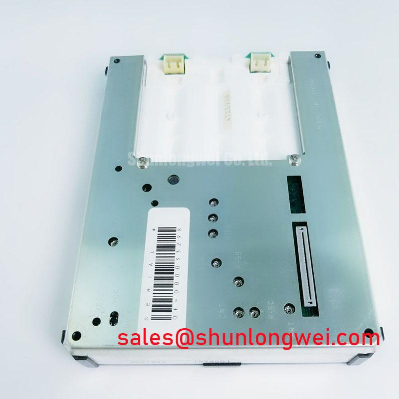
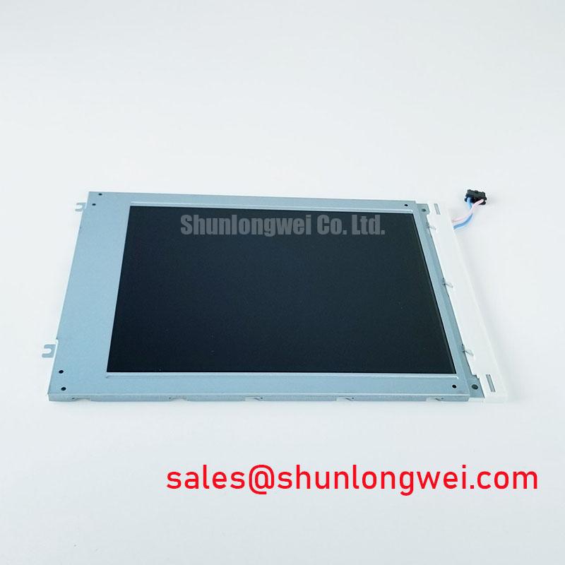
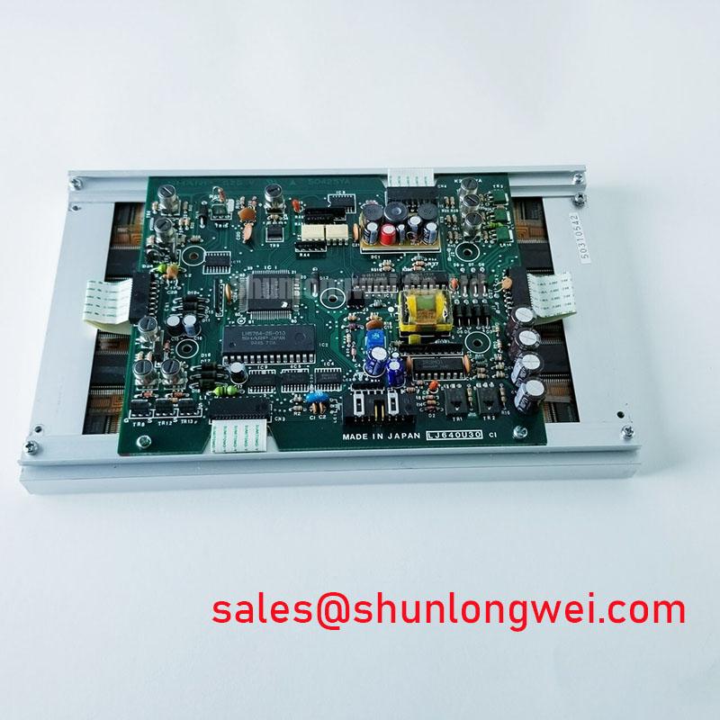
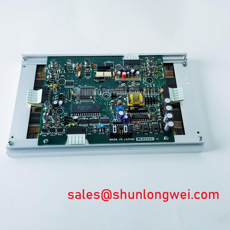
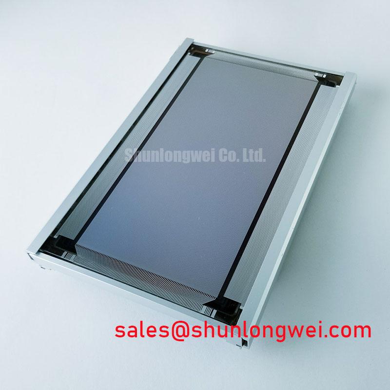
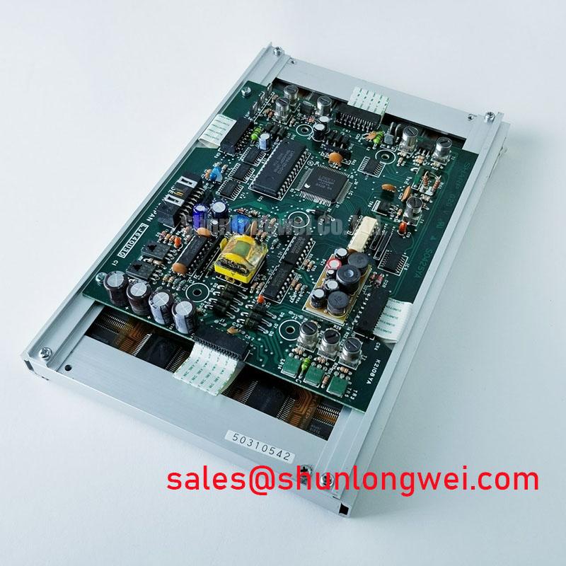
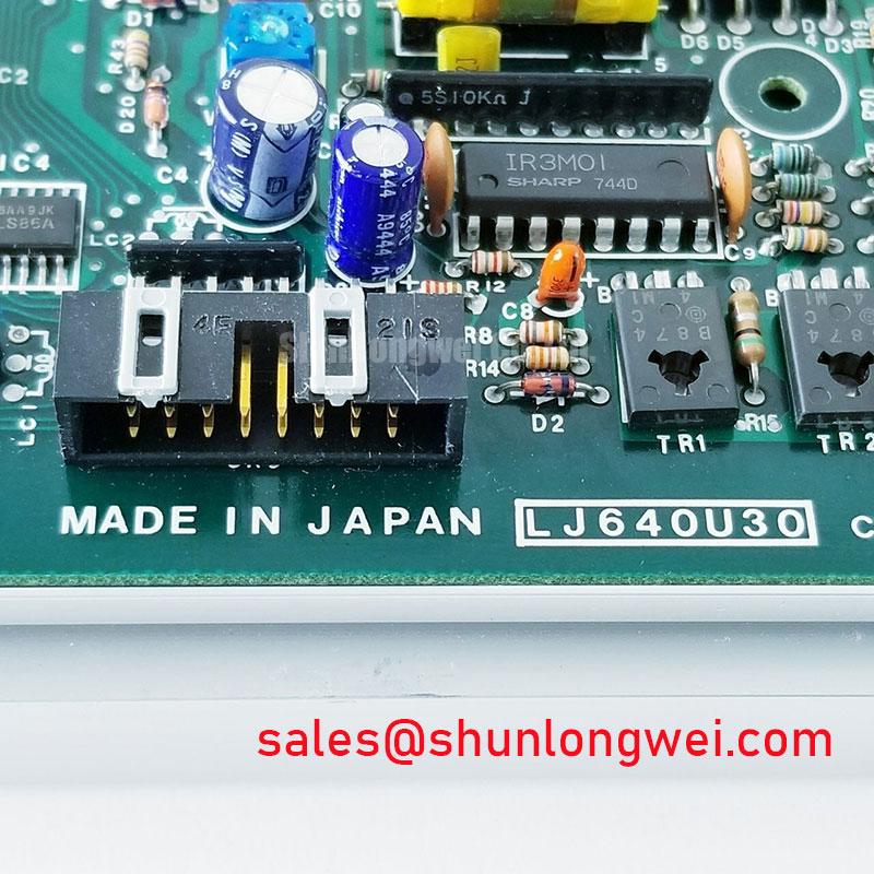
Begin a replacement evaluation by checking the LJ640U30 label, inspecting the TFT LCD module for cracked glass or frame distortion, and comparing the original display connector and mounting points with the equipment documentation. The available factory identification confirms Sharp as the manufacturer, the product category as an industrial grade LCD and HMI panel, and the construction as a TFT LCD display module. Electrical interface values, dimensions, optical ratings, and backlight details should be confirmed against the original panel documentation before power is applied.
| Parameter | Available specification status |
| Model | LJ640U30 |
| Manufacturer | Sharp |
| Product category | Industrial grade LCD and HMI panel |
| Construction | TFT LCD display module |
| Specification status | Product identity verified; detailed specifications unavailable |
The supplied factory data does not confirm a native supply voltage, connector pinout, resolution, active area, luminance, viewing angle, response time, backlight type, or environmental rating. Those values should not be inferred from the model number. The Sharp Display Solutions Official Portal can provide useful manufacturer context, while the equipment service manual remains the controlling reference for a field replacement.
VESA vs. JEIDA Data Mapping Alignment and Even or Odd Channel Signal Integrity
Before connecting the display, identify whether the host uses LVDS, TTL, or another panel interface, then compare the connector position, signal names, data mapping, clock polarity, and channel arrangement with the original documentation. A panel that fits mechanically can still produce incorrect colors, split-screen imagery, unstable synchronization, or a blank image when the host format does not match the display input.
JEIDA and VESA mapping should be treated as separate verification items rather than interchangeable terminology. Engineers should check the bit order for each color channel, the treatment of the most significant data bits, even and odd channel allocation, and the relationship between the pixel clock and data pairs. The required logic supply voltage must also be verified from the original panel documentation. The values 3.3 V and 5.0 V should not be treated as interchangeable options for this model without documentary confirmation.
For an LVDS implementation, the system designer should control differential routing symmetry, maintain the intended characteristic impedance of the host interconnect, and assess clock and data skew with the complete cable, connector, and controller assembly. A nominal 100 ohm differential target is a common high speed interface design consideration, not a confirmed LJ640U30 factory specification. During bring up, compare the suspected display path with a known good assembly using an oscilloscope, checking for abnormal ringing, intermittent clock activity, or channel imbalance.
Optical evaluation also belongs in the acceptance test. Contrast stability under direct ambient light, surface reflection, and anti glare performance depend on the complete display stack and enclosure. Any contrast target under high ambient illumination must be verified from an applicable optical datasheet or measured on the assembled unit; it is not assigned here as an official LJ640U30 value. Potential use in a high precision surgical navigation or ultrasound diagnostic display should therefore remain subject to system level image quality, cleaning, enclosure, and regulatory verification.
💡 Pro Tip: Disconnect power before removing the panel cable, because live insertion can expose the display interface to transient contact conditions outside the documented operating limits.
High Humidity Storage Margins and Delamination Prevention Protocols
Storage and installation checks should begin with the enclosure rather than with assumptions about the LCD cell. Inspect the perimeter, polarizer surface, connector area, and frame for moisture residue, optical haze, adhesive lifting, or pressure marks. If the unit has been stored in a humid location, allow the complete assembly to stabilize under the procedure specified by the equipment manufacturer before applying power.
The supplied data does not assign a 60°C and 90% relative humidity storage rating to the LJ640U30. Such a condition should be used only when supported by the applicable Sharp documentation or a qualified system test plan. Delamination risk is influenced by storage history, thermal transitions, enclosure sealing, mechanical stress, cleaning agents, and the construction of the installed panel. A visual inspection before and after environmental exposure is more defensible than assigning an unsupported lifetime or failure probability.
Sub-zero operation can alter liquid crystal response behavior and may produce visible image lag until the panel reaches a suitable stabilized condition. This is a design consideration for equipment exposed to cold transport or outdoor service, not a confirmed operating limit for this model. Engineers should verify the documented operating and storage temperature ranges, then assess gray transition behavior, startup uniformity, and image recovery over the actual system temperature profile.
In a high EMI factory environment, the display cable should be routed away from switching power loops and protected from unnecessary ground reference changes. Differential pair impedance and skew should be controlled across the full signal path, including the controller board, cable, connector, and panel interface. A 100 ohm target with a 10 percent tolerance and a 50 ps skew budget may be used as a preliminary high speed design consideration only when it matches the controller and interface documentation. Final acceptance should rely on signal measurements and image stability testing.
For broader enclosure, sealing, thermal, and HMI integration considerations, engineers can consult the Industrial Display and HMI Solutions engineering guide. It should supplement, not replace, the specific Sharp panel documentation.
Optical Luminance Degradation and CCFL to LED Modernization Evaluation
Do not assume the backlight technology from the model number alone. The available LJ640U30 factory context identifies a TFT LCD display module but does not confirm whether the installed backlight is CCFL or LED, nor does it provide an official luminance decay curve, half life, MTBF, ignition voltage, or PWM specification.
If the original assembly uses a cold cathode fluorescent lamp, the service engineer should identify the inverter, lamp connector, high voltage insulation arrangement, and start behavior before considering any retrofit. A CCFL ignition-voltage requirement is a system level design reference for the applicable circuit, not an LJ640U30 rating. Replacing that circuit with an LED solution requires assessment of optical uniformity, mechanical fit, thermal dissipation, driver protection, dimming compatibility, and electromagnetic noise.
When a constant current LED driver is evaluated, the driver current, enable logic, dimming method, and fault response must be matched to the actual retrofit assembly. PWM dimming ratio and frequency should be selected based on the replacement backlight and controller documentation, not assigned as native LJ640U30 specifications. Duty cycle linearity should be checked with a photometric instrument and by observing text, gradients, and low brightness scenes for visible flicker.
Acoustic buzz can originate in an inverter, transformer, mounting surface, or retrofit driver and should be localized with the display operating through several brightness levels. Luminance degradation should be measured on the complete display assembly at controlled brightness and temperature. Any claimed backlight life or MTBF requires a manufacturer test report or recognized reliability source; no such field life figure is assigned here.
Single Vertical Hairline Defect and Sub Pixel Column Driver Localization
A single vertical line should first be documented with full screen red, green, blue, white, black, and gray images. Record whether the line remains fixed, changes intensity with image content, or disappears during startup. This multi-color bench test helps separate an input mapping problem, display drive abnormality, backlight nonuniformity, and a localized column response issue without assigning a single cause prematurely.
Next, inspect the cable seating, connector contacts, controller output, and chassis pressure around the display perimeter. Compare the suspected channel with a known good signal path where available. An oscilloscope can help identify missing or unstable clock and data activity, but a stable digital waveform does not by itself prove that the panel cell or column drive path is sound.
A 45 degree flashlight inspection in a darkened environment can reveal whether a suspected mark is a surface feature, an inactive image column, or a backlight shadow. Change the viewing angle without pressing the glass. Pressure testing is not recommended because it can create additional display damage and can obscure the original fault condition. A line that remains spatially fixed across primary colors may warrant panel level evaluation, while intermittent behavior should also prompt checks of cable strain, connector retention, grounding, and controller timing.
The supplied information does not establish a COG driver construction, allowable repair method, or approved panel level rework procedure for this model. Avoid describing a micro fracture as confirmed without microscopic evidence and manufacturer guidance. If a replacement assessment is required, compare connector geometry, active image position, mounting features, optical behavior, and controller compatibility with the original assembly. The LM057QC1T08 may be reviewed as a separate display option for engineering comparison, but it should not be treated as a drop in substitute unless the system integrator verifies every electrical, mechanical, optical, and software interface.