Content last revised on September 23, 2026
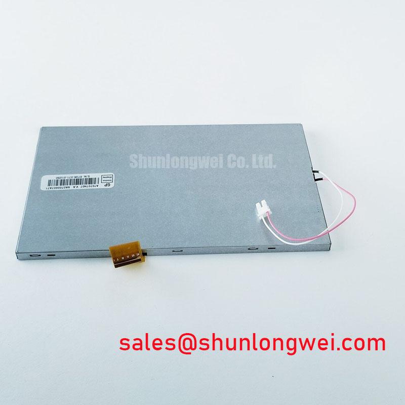
Mechanical Stress and Optical Fault Prevention for AT070TN07 V.A.
Before fitting AT070TN07 V.A, place the removed display and the replacement module on a clean, grounded work surface, inspect the viewing area under oblique light, and compare the connector orientation with the original assembly. This Ampire TFT LCD Display Module is intended for integration into an LCD/HMI system. The system integrator should confirm all electrical, optical, connector, and mechanical requirements against the original panel documentation before interchange.
A practical bench check begins with a controlled primary colour sequence. Drive known red, green, blue, white, grey, and black fields from the existing controller or a validated test source. Observe whether a defect remains fixed to a region of the panel, changes with the image content, or disappears when the display is viewed under altered ambient light. A flashlight held at approximately 45 degrees can help distinguish an image path issue from an illumination related condition. This is a diagnostic aid, not a conclusive failure classification.
Do not flex the display while testing. Localized pressure around the active area, connector region, bezel openings, or mounting ears can alter visible artefacts temporarily and make a stable assessment difficult. Where a line, colour band, or intermittent image is present, compare the result with a known good controller output and cable before attributing the condition to the display assembly.
For installations using differential display signalling, controlled impedance and pair length matching are Design Considerations, not confirmed factory specifications of AT070TN07 V.A. The display interface type, transmitter standard, signal mapping, termination approach, and timing limits must be verified from the original equipment documentation. In electrically noisy cabinet environments, routing signal conductors away from switching power paths can help reduce coupling, subject to system level signal integrity measurements.
⚠️ Maintenance Note: Inspect enclosure gaskets, cable strain relief, and ventilation paths during scheduled service because moisture retention and uneven mounting load can affect the complete display assembly.
Normally White TN Grayscale Inversion Mitigation & Optimal Viewing Direction Alignment
With the module powered from the original validated system, inspect grey ramps and low contrast menu fields from the normal operator position before final fastening. The specified product category identifies AT070TN07 V.A as an industrial grade LCD/HMI panel, but the integrator should verify the panel mode, viewing direction, luminance, colour performance, and surface treatment from the original panel documentation. These characteristics must not be inferred solely from a similar looking 7 inch display.
TN display technologies can exhibit viewing direction dependence in some configurations, particularly when grey tones are assessed from above or below the intended line of sight. IPS and MVA technologies are often evaluated for more symmetric viewing characteristics, but their typical performance must not be used as a substitute specification for this Ampire module. Position the panel in its intended bezel orientation, then assess navigation symbols, alarm colours, text edges, and dark menu backgrounds from the actual operating angle.
Surface glare is also an enclosure level consideration. A cover lens, window coating, air gap, and bezel geometry can change reflections seen by the operator. For equipment such as a marine radar or navigation bridge console, engineers may evaluate contrast under strong ambient illumination, subject to the equipment enclosure, sealing design, and applicable marine system requirements. The module itself should not be represented as independently certified for the completed console environment.
Clock stability, data hold time, and transmitter timing are governed by the host interface and the validated panel timing requirements. If a display shows occasional colour noise, unstable pixels, or content dependent disturbance, verify the controller waveform at the panel connector and compare it with a known good signal path. Avoid modifying timing values based on generic panel guidance alone.
For broader discussion of panel selection, sealing, integration exposure, and service planning, see Industrial Display & HMI Solutions. Industry display portfolios, including those presented by Innolux Corporation, also show why mechanical format and interface validation remain essential when evaluating industrial display assemblies.
Preventing Localized Light Guide Plate LGP Compression Warp on Dark Screen Fields
Check dark screen fields before closing the equipment bezel. A uniform black or dark grey test image can reveal edge pressure, local brightness variation, reflection from a cover window, or contamination between the display and front assembly. Such observations do not establish an internal panel cause by themselves. They provide a repeatable baseline for comparing the removed display, replacement module, and completed assembly.
The outside bezel should support the module evenly without loading the active viewing region. Fastener count, screw size, tightening sequence, shoulder design, and compression limits are characteristics of the host equipment, not published module parameters in the supplied factory data. As a Design Consideration, use a balanced cross pattern where the mechanical drawing for the equipment calls for multiple mounting points, and verify that the bezel does not introduce panel twist after the final cover is installed.
Do not rely on a generic torque value as an official rating for AT070TN07 V.A. The final fastening requirement is determined by the host chassis, threaded material, spacer stack, gasket design, and mounting hardware. After fastening, repeat the dark field inspection from the intended viewing direction. If an optical irregularity changes after enclosure assembly, release the mounting load, inspect contact surfaces and spacers, then reassemble according to the equipment maker’s mechanical process.
Backlight brightness retention, if applicable to the original assembly, depends on the actual illumination configuration, driver current regulation, ambient temperature, duty cycle, and enclosure thermal conditions. No operating lifetime or brightness decay figure should be assigned to this module without the relevant official specification or qualified test data. Keep cooling paths clear and examine nearby power supplies for heat transfer into the display cavity during preventive maintenance.
Where condensation is possible, inspect the enclosure seal, cable entry points, and air exchange route before replacing the panel. Allow equipment to reach a stable temperature before energizing a display that has been exposed to a significant temperature transition. This supports objective service practice without assuming a specific environmental rating for the module.
Controlled 100 Ohm Differential Impedance Flex Routing to Suppress High Frequency Jitter
Verify connector seating and the original display cable routing before applying power to AT070TN07 V.A. The supplied official information identifies the product as an Ampire TFT LCD display module, but it does not establish a logic supply voltage, interface family, power sequencing requirement, differential impedance value, or JEIDA and VESA mapping. The system integrator should verify these requirements from the original panel documentation and the host controller schematic.
Where the equipment uses a differential interface, controlled pair routing can be a useful Design Consideration for limiting waveform degradation caused by impedance discontinuities, pair separation, sharp bends, or proximity to switching conductors. The correct characteristic impedance is determined by the confirmed interface standard and cable construction. Do not apply a nominal routing value unless it matches the validated controller and panel requirements.
Power sequencing must be checked as a complete system event. Observe logic rails, enable controls, panel data activity, and backlight control where present, using the original equipment sequence as the reference. A split image, unstable start, white screen, or intermittent picture can arise from more than one condition, including cable contact, controller timing, supply behaviour, display settings, or mechanical stress. Isolate variables one at a time and retain comparison results from a known good assembly.
The external article on hot carrier injection degradation describes a semiconductor wear mechanism relevant to transistor devices, but it does not define the electrical ratings, display lifetime, or reliability of this LCD module. For AT070TN07 V.A service work, the appropriate evidence remains the original equipment documentation, confirmed interface measurements, and the official module specification.
When assessing compatibility for a marine radar or navigation bridge console, verify the completed terminal rather than treating the panel as a standalone environmental system. Enclosure sealing, cover lens reflection, grounding, cable routing, thermal behaviour, and controller output all influence the service result.