


Content last revised on September 25, 2026
Preventing Frame Lag and Image Smearing in Cryogenic Storage and Outdoor Industrial Facilities
When an industrial panel presents slow transitions, trailing text, or temporary tonal changes after exposure to low ambient temperatures, maintenance personnel should first separate display-cell behavior from host-system timing, power, and cable faults. Liquid-crystal response can change with temperature, while moisture, stressed mounting hardware, connector oxidation, and unstable display supply conditions can create similar visual symptoms. The correct service approach is to allow the equipment to reach a stable, dry temperature before judging image response.
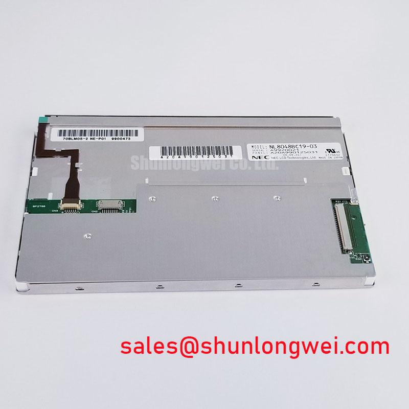
The verified product profile for the NL8048BC19-03 NEC TFT-LCD module does not establish a published operating-temperature range, gray-to-gray response time, contrast ratio, sunlight readability rating, anti-glare coating type, or perimeter seal material. These values should therefore not be assumed for this specific model. A system integrator should verify the required environmental limits from the original panel documentation and assess whether the machine enclosure provides adequate protection against condensation, dust ingress, direct solar heating, and vibration.
For equipment placed in cold stores, yard kiosks, or exposed control cabins, a useful Design Consideration is to inspect the display only after the enclosure has stabilized. Condensation on a connector, cable, or driver board can produce intermittent behavior that resembles optical lag. Check for water marks around the bezel, uneven contact between the panel frame and its gasket, and signs that the mounting stack has been tightened unevenly. Uneven frame loading can create local light variation, commonly described as mura, even where the underlying image data remains correct.
Where strong ambient light affects readability, the panel surface and front-window assembly should be evaluated together. A high-contrast image on a bench may become difficult to read through a scratched protective window, a dirty anti-reflective cover, or an enclosure angle that catches the sun. The system engineer should verify the required optical performance under the actual installation illumination rather than assigning a sunlight-readability figure that has not been published for this module.
⚠️ Maintenance Note: Inspect the display gasket, mounting hardware, and enclosure ventilation path during scheduled service because trapped moisture and uneven mechanical loading can affect both image appearance and long-term assembly condition.
Suppressing Pixel Jitter and Horizontal White Lines Associated with Adjacent 400V Motor Drives
When horizontal white bands, intermittent pixel movement, or image instability appear after a nearby motor drive starts switching, begin at the physical signal route rather than replacing the panel immediately. Disconnect power safely, inspect the display connector and cable seating, examine the cable path near power conductors, and compare the screen behavior with the drive inactive and active. A visible disturbance may arise from common-mode interference, a marginal ground reference, cable damage, unstable host timing, or a display-side connector issue.
The official verified profile identifies the NL8048BC19-03 as a TFT-LCD module but does not confirm its signal interface, connector pinout, differential-pair impedance requirement, shield termination method, or timing limits. It would be inappropriate to label this model as LVDS, TTL, or any other interface without the original NEC panel documentation. Before repairing an existing machine, technicians should compare the installed cable assembly and mating connector with the equipment schematic and service material.
As a Design Consideration for industrial display harnesses, route low-level display signaling away from motor output leads, braking circuits, contactors, and high-current switching paths where practical. If the original system uses a shielded display cable, restore its shield continuity according to the equipment design rather than adding arbitrary ground points. Shield termination can affect noise behavior, and the chassis arrangement must be validated within the complete machine.
Where a documented differential display link is present, impedance continuity and pair-to-pair timing alignment are system-level concerns. Engineers often evaluate the cable, connector, and board trace as one signal path, then verify waveform quality against a known-good unit with suitable measurement equipment. A horizontal artifact does not prove that the TFT glass is defective. It may indicate a disturbed signal reference or degraded connection, so observation should include cable flexing, connector reseating, supply monitoring, and comparison with a verified host controller.
Industrial service teams evaluating similar NEC panel families may also review the NL10276BC16-06 as a separate display-module reference. It is not an automatic replacement for the NL8048BC19-03; mechanical fit, interface definition, power sequencing, optical requirements, and firmware compatibility must be confirmed independently.
Backlight Driving, Dimming, and Flicker Suppression
Backlight diagnosis should begin with the host equipment documentation and the original display assembly rather than an assumption about lamp technology. The verified factory information for the NL8048BC19-03 does not state whether the module uses a WLED backlight, CCFL backlight, or another illumination arrangement. It also does not publish a backlight input voltage, current requirement, dimming method, brightness level, lifetime rating, or protection behavior. These characteristics must be confirmed from original NEC documentation before any driver board, inverter, or cable assembly is selected.
A screen that has no visible image can originate from several different areas. The host controller may not be sending valid video data, panel logic power may be absent, the backlight circuit may not be enabled, a cable may be loose, or the display itself may have an internal fault. Service work should distinguish between a faint image under controlled inspection, a completely inactive panel, and an image that appears only intermittently. These observations help guide the next measurement without assigning a single cause prematurely.
An Engineering Recommendation is to verify panel power sequencing, enable signals, and dimming control only against the host schematic or documented replacement procedure. Introducing an unverified backlight driver or applying guessed power conditions can damage a display assembly. If an external driver is used in the machine architecture, confirm its output characteristics, protection response, and connector compatibility with the original system design.
Flicker complaints also require careful separation of display, backlight, protective window, and human-perception factors. Visual instability can become more obvious when a camera is used for inspection, when an enclosure window reflects moving light, or when the host controller updates images irregularly. Where PWM dimming is documented for the installed display system, its frequency and duty behavior should be validated at the complete assembly level. No PWM frequency, dimming ratio, acoustic performance, or service-life figure is claimed here for the NL8048BC19-03.
For a broader explanation of panel interfaces, optical behavior, and practical industrial LCD selection factors, see The Ultimate Guide to Industrial TFT LCD Technology. The guide supports engineering assessment but does not replace the model-specific NEC documentation required for this panel.
Viewing Performance for Multi-Angle Consoles
Evaluate viewing performance with the display installed in its intended bezel and at the operator’s normal position. Color shift, grayscale variation, reflective glare, or apparent loss of contrast can be caused by panel viewing characteristics, the chosen mounting angle, the enclosure window, surface contamination, or ambient light. For multi-angle consoles, the visible result should be assessed from the actual operator positions instead of relying only on a bench image viewed head-on.
The official verified information for the NL8048BC19-03 NEC LCD display does not identify the liquid-crystal mode as IPS, MVA, TN, or another technology. It also does not provide viewing-angle figures, anti-glare treatment, anti-reflective performance, contrast ratio, or brightness data. Claims of a symmetric viewing cone or a specific optical coating would therefore exceed the available verified specification.
As a Design Consideration, preserve the original panel orientation and bezel geometry during a repair. A mechanically compatible display with a different optical structure can alter how text, warning colors, and dark areas appear across the operator’s field of view. This is especially relevant when a display is evaluated for telematics consoles in heavy earthmoving equipment, where enclosure vibration, changing sunlight, and operator seating position should all be considered during compatibility review.
Do not treat a touch overlay as part of the NL8048BC19-03 unless it is separately documented in the original equipment assembly. Capacitive and resistive touch systems have different behavior with gloves, water, protective films, and grounding arrangements, but the verified factory description for this product identifies a TFT-LCD display module only. If a machine has touch input, verify whether the touch sensor, controller, protective glass, and display are separate service items.
Before approving a replacement installation, confirm the NEC part number, host interface documentation, connector orientation, mounting pattern, front-bezel fit, power sequencing requirements, and expected optical behavior in the complete equipment assembly. This preserves a clear boundary between the verified NL8048BC19-03 module identity and system-specific integration decisions.

