Content last revised on October 12, 2026
NL8048BC19-08D Display Inspection and Replacement Evaluation
With the terminal isolated from power, inspect the display cable seating, connector latch, and bezel pressure before attributing a dark or uneven image to the NL8048BC19-08D. Photograph the installed cable orientation and record whether the fault appears immediately, after warm-up, or only when nearby equipment operates. Those observations help separate an image-generation problem from a backlight, connection, or installation problem.
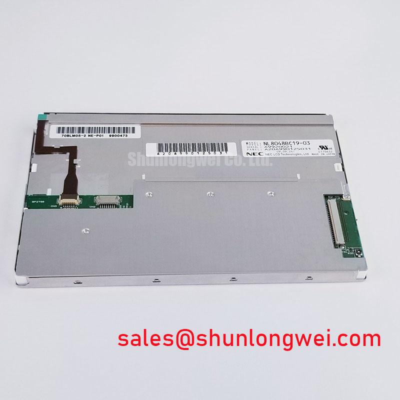
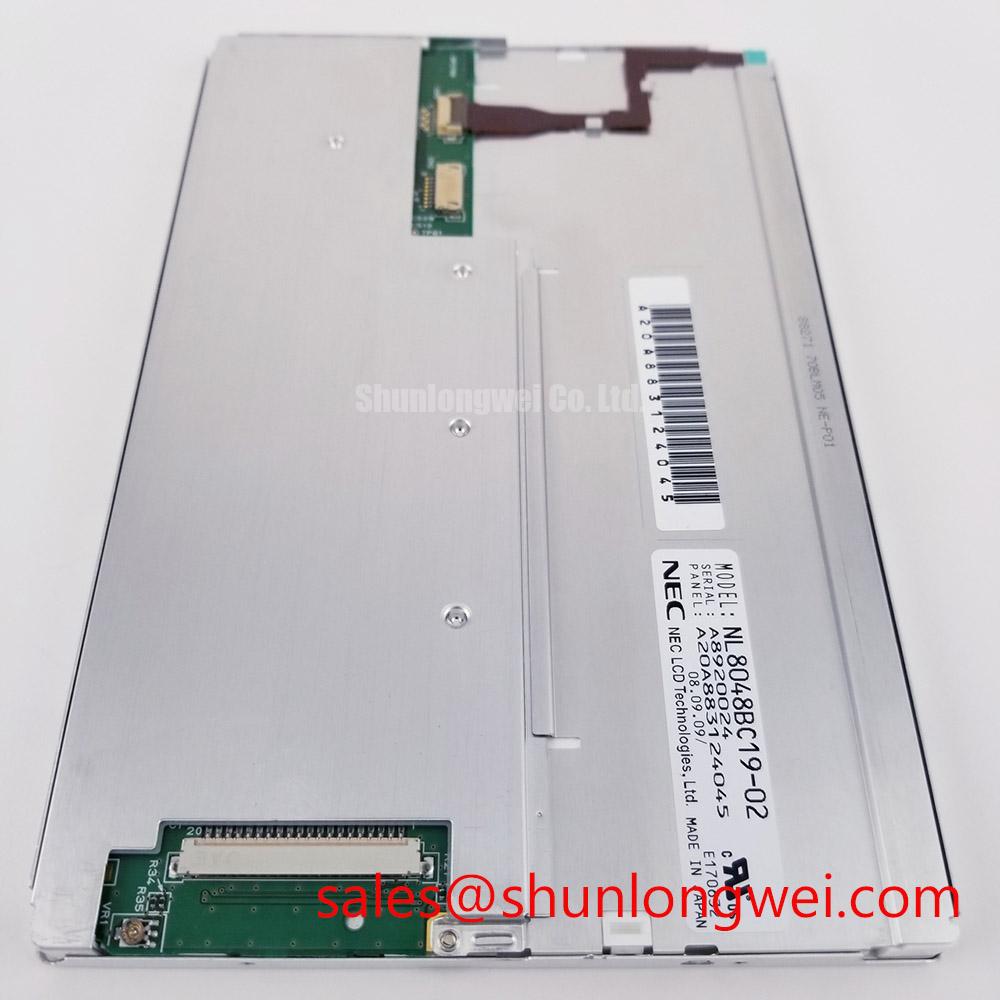
The NL8048BC19-08D is an NEC TFT-LCD active-matrix color display module in the industrial LCD/HMI panel category. For replacement evaluation, establish the electrical and mechanical baseline from the original panel documentation: supply requirements, connector pinout, display timing, backlight connections, and mounting dimensions. Treat these as acceptance criteria rather than inferring compatibility from the model name or connector appearance.
Suppressing Localized Thermal Gradients to Prevent Chronic Optical Yellowing
Compare the location of discoloration with nearby heat sources, mounting contacts, and restricted ventilation paths. A photograph of a uniform test image taken at cold start and again after thermal stabilization can reveal whether the visible change follows temperature. Keep brightness, image content, viewing position, and ambient illumination consistent so that reflections do not obscure the comparison.
Design Consideration: Where the enclosure concentrates heat along a narrow display edge, evaluate a heat-spreading path through the supporting chassis. Any additional rail should contact an appropriate structural surface without loading the glass, obstructing connectors, or distorting the bezel. Its dimensions and attachment method belong to the enclosure design and should be validated through temperature measurements and mechanical clearance checks.
Yellowing alone does not establish the affected material or failure mechanism. Compare neutral gray and white images across the screen, then inspect the external protective window separately where the assembly permits. A tinted cover, contamination, uneven illumination, or pressure-related optical change can produce overlapping symptoms. Avoid assigning a specific internal polymer or predicting remaining backlight life from appearance.
For daylight evaluation, assess the complete optical stack under representative illumination. Anti-glare treatment can reduce distinct reflections while changing perceived sharpness; anti-reflection treatment addresses reflection through a different optical mechanism. Neither is established here as a supplied feature. The manufacturer's NEC Industrial TFT Display Solutions resource provides industrial-display context, while acceptance testing should use the actual enclosure window and viewing geometry.
High-Voltage Striking Potential and Secondary Coil Insulation Testing
Separate backlight operation from image generation before investigating the illumination power stage. Under controlled ambient light, inspect the screen for a faint changing image while the host updates its content. This observation can help direct testing toward the illumination path, but it is not sufficient by itself to identify a failed driver or display module.
Engineering Recommendation: Trace the installed backlight circuit from its documented power input through enable, brightness control, and any fault output. Capture these signals during startup and at the moment illumination disappears. A shutdown can reflect a supply disturbance, an interrupted load connection, a control command, or a protection response; compare the sequence with the driver documentation before replacing parts.
High-voltage ignition and transformer-secondary insulation tests apply only to an installed circuit documented as requiring them. They are not ratings established for the NL8048BC19-08D by this product description. Where such circuitry exists, use appropriately rated measurement equipment and the equipment manufacturer's isolation procedure. Do not apply an insulation tester across an assembled display or its electronics without an explicitly approved test method.
For a documented constant-current backlight circuit, assess current regulation, connector continuity, and protection behavior using the driver's specified operating conditions. Open-load and short-circuit responses are driver-specific. Audible noise and brightness instability should be correlated with supply ripple and dimming commands rather than treated as proof of a particular component failure. Dimming frequency, duty-cycle limits, and any service-life claim require their own documented basis.
Digital RGB Bus Synchronization and Logic Power Rail Verification
Map the host connector to the panel connector before probing the signal path. Record each supply, return, control, and image-data connection from the equipment schematic. Matching connector pitch or pin count does not establish matching assignments, and an adapter board can change the interface between the host and the display.
Design Consideration: Measure the panel supply at its connector during startup and during the reported fault, using the specified signal reference. Check whether image signals become active in the sequence required by the panel. A steady reading at the upstream power supply can miss a voltage disturbance across a cable, connector, or switched distribution path.
Keep parallel RGB and differential-interface checks separate. Parallel-bus evaluation concerns clock-to-data relationships and control-signal timing; a documented differential link requires evaluation of its paired conductors and receiver conditions. JEIDA/VESA mapping is relevant only where the installed interface specifies it. Do not assign interface type, color depth, impedance, or timing limits to this model without its corresponding specification.
When comparing the NL8048BC19-08D with another display, assess active area, outline, mounting points, electrical interface, timing, and backlight requirements independently. The NLB150XG01L-01BD can be included in a documented comparison, but its presence in a product catalog does not establish interchangeability. For a marine radar or navigation bridge console evaluation, assess daylight readability and enclosure protection separately from basic electrical compatibility; neither follows automatically from the industrial-panel category.
Shielded FFC/FPC Cable Grounding and Connector-Shell Continuity
Follow the installed display cable route and inspect strain relief, bend damage, latch engagement, and proximity to electrically noisy wiring. Where a shielded harness is specified, check its termination against the equipment drawing. A flat flexible cable does not inherently provide shielding, and connector-shell bonding should not be assumed from appearance.
Field Alert: Disconnect equipment power and follow its discharge procedure before reseating display or backlight connectors.
Engineering Recommendation: Correlate pixel disturbance or horizontal bands with machine operating states before modifying the harness. Compare observations with a known-good signal path where available, and measure relevant supply and signal behavior with suitable probes. Added ferrites or altered grounding can change circuit behavior; their suitability should be established through system testing rather than prescribed as universal remedies.
The Industrial Display & HMI Solutions guide provides broader integration context for separating display, cable, power, and enclosure issues. If the assembly includes a touch overlay, diagnose it independently of the LCD image: glove response, wet-surface behavior, and controller calibration belong to the installed touch system. After cable work, retest image stability and touch response under the operating conditions that originally reproduced the fault.