

Content last revised on September 23, 2026
Dynamic Contrast Ratio Stabilization and Liquid Crystal Temperature Tracking
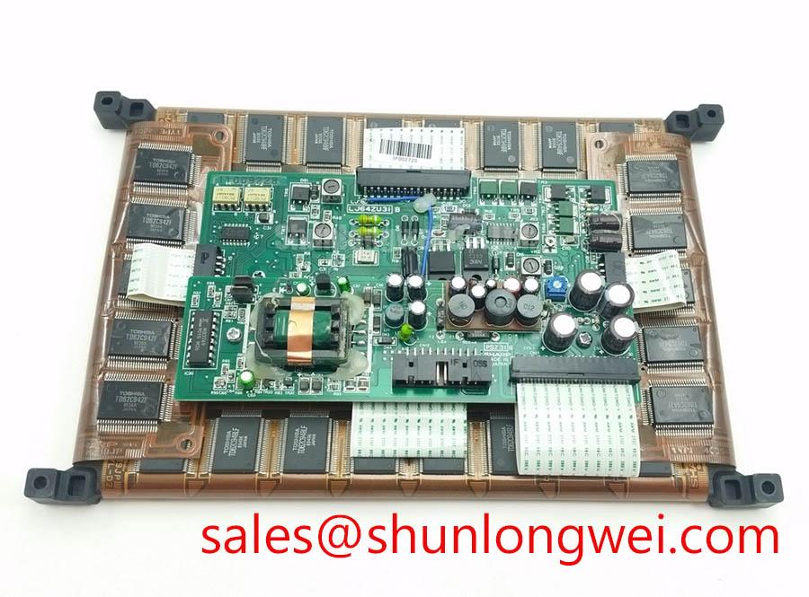
Isolate the display power, inspect the TFT-LCD module and its flexible connections, then compare the nameplate and original panel documentation before applying power. The LJ64ZU31 is identified here as a Sharp Industrial Grade LCD/HMI Panel with a TFT-LCD Display Module package. Electrical ratings, resolution, interface pinout, viewing angle, backlight configuration, and mechanical dimensions should be confirmed from the original equipment documentation before replacement.
When a bridge console or outdoor monitoring panel shows washed-out text, shadowing, or unstable grayscale, begin by checking the optical environment and the panel supply path rather than assuming a liquid-crystal failure. Direct sunlight, a damaged surface layer, incorrect display settings, and unstable power can produce similar symptoms. The available factory context for LJ64ZU31 does not confirm a specific contrast ratio, anti-glare treatment, viewing cone, or low-temperature response curve, so those values must not be treated as model specifications.
TN, IPS, and MVA panels can exhibit different grayscale behavior as temperature changes, but the panel technology for this model is not stated in the supplied factory data. A Design Consideration for cold or exposed installations is to verify the manufacturer’s temperature range, response-time limits, and any approved enclosure heating method. If a heater strip is used in the equipment, its control should be assessed against the panel documentation and actual surface temperature. Engineers evaluating a harsh marine radar or navigation bridge console should also confirm sealing, condensation control, optical readability, and salt-air protection at the complete enclosure level.
Reference information from the Sharp Display Solutions Official Portal and Sharp Devices Europe Industrial Display Solutions may help establish the correct documentation route for display technology and operating conditions.
Shielded FFC and FPC Grounding across Connector Shells
For a black screen, intermittent image, pixel jitter, or horizontal noise bands, inspect the FFC or FPC seating, connector latch, cable bend radius, and chassis bonding before changing the panel. A cable that appears mechanically inserted may still have uneven contact pressure or contamination at the mating surface. Compare the suspect signal path with a known-good assembly using the equipment maker’s approved test procedure.
Shield termination is a system-level Design Consideration. The integrator should establish whether the cable shield is bonded at one or both ends, how the connector shell is referenced to chassis, and whether common-mode filtering is already present near variable-frequency motor drives. Do not assume that a 360-degree shield termination, ferrite component, PWM frequency, or dimming duty-cycle range belongs to LJ64ZU31; none of these values is confirmed in the supplied factory specification. Any proposed filter must be checked for its effect on signal integrity, conducted noise, and display brightness control.
⚠️ Field Alert: Disconnect power and allow the equipment discharge procedure to finish before inserting or removing a display cable, because signal-pin contact during powered connection can damage the interface or create misleading troubleshooting symptoms.
20-Pin or 30-Pin Differential LVDS Timing and Pixel Clock Verification
The connector count and interface mapping for LJ64ZU31 are not provided in the verified product data. The system integrator should verify the original panel documentation for the required supply voltage, connector type, pin assignment, differential pair arrangement, data mapping, and pixel clock conditions. Do not substitute a 20-pin or 30-pin cable based only on physical fit.
During diagnosis, check whether the display controller is delivering stable power and a valid differential signal sequence. An oscilloscope comparison with a known-good signal path can help identify impedance discontinuity, pair reversal, excessive skew, missing clock activity, or incorrect JEIDA and VESA mapping. The commonly used differential routing target of controlled characteristic impedance is a system-board design requirement, not an LJ64ZU31 factory rating. Rise-time limits and power-on sequencing must likewise be taken from the controller and panel documentation rather than inferred from a general LCD rule.
For high ambient light, optical contrast should be measured in the completed bezel and cover-glass assembly. A laboratory value cannot be transferred directly to a navigation console without considering reflections, viewing direction, surface treatment, and enclosure lighting. The neutral replacement reference LM057QC1T08 may be reviewed separately when the original system documentation permits cross-model evaluation; physical fit and electrical compatibility still require verification.
Edge-Lit LED Rail Thermal Management and Optical Preservation
The supplied factory data identifies LJ64ZU31 as a TFT-LCD Display Module but does not confirm an LED backlight, edge-light construction, light-guide material, rail geometry, L70 or B50 life data, or allowable optical temperature. These characteristics must be confirmed before designing a replacement backlight circuit or heat-spreader arrangement. A backlight fault should first be separated from a video fault by checking the controller output, backlight enable path, current regulation, and panel-side connectors according to the equipment schematic.
As a Design Consideration, thermal paths should avoid concentrating heat at one display edge or transferring mechanical stress into the panel frame. The enclosure designer should verify temperature at the display surface and mounting points during maximum brightness, startup, and fault conditions. Any aluminum spreader, thermal interface material, or fastener method must be selected from the approved mechanical documentation; the supplied data does not establish a material, coating, thickness, or installation torque for this model.
The complementary display reference LQ10D321 can be considered only where the system schematic and original documentation show a relevant relationship. Broader enclosure, cable, and environmental integration guidance is available through Industrial Display & HMI Solutions. For marine radar or bridge-console evaluation, final acceptance should be based on the complete assembly’s optical, electrical, mechanical, and environmental test results rather than the panel category alone.