

Content last revised on September 24, 2026
M185XTN01.3 AUO Industrial Grade LCD/HMI Panel
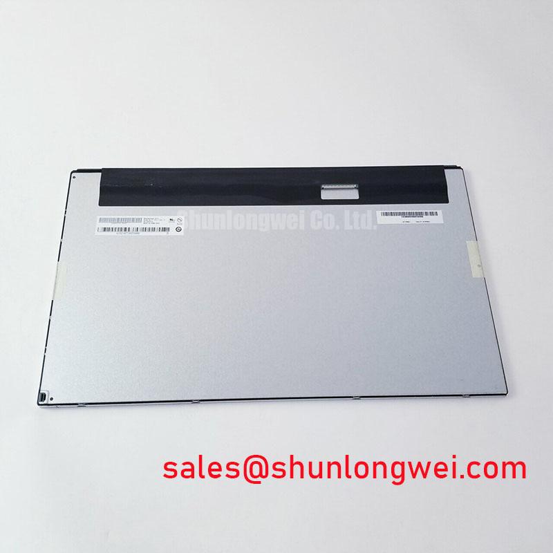
Before powering a replacement panel, compare the nameplate, connector position, mechanical envelope, and original system documentation against M185XTN01.3 to confirm that the installed unit is the correct AUO display module.
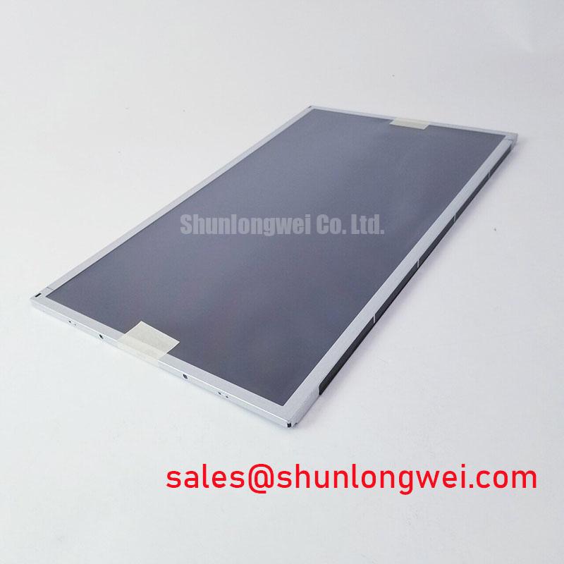
M185XTN01.3 is an AUO Industrial Grade LCD/HMI Panel supplied as a TFT-LCD Display Module. The available factory information identifies the manufacturer, product category, module construction, and official specification status. Panel resolution, active-area dimensions, interface pinout, supply voltage, backlight electrical data, and mounting drawings should be verified from the original AUO documentation or the equipment service manual before installation.
| Model | M185XTN01.3 |
| Manufacturer | AUO |
| Product category | Industrial Grade LCD/HMI Panel |
| Module type | TFT-LCD Display Module |
| Specification status | Factory information available; detailed specifications require verification |
This part may be evaluated for industrial HMI assemblies, operator stations, and monitoring terminals, including display sections used in hazardous-area equipment. The complete enclosure, electrical protection, thermal management, and hazardous-location certification remain system-level responsibilities. The LCD module itself must not be treated as independently certified for a complete Zone 2 installation.
Preventing Localized Light Guide Plate Compression Warp on Dark Screen Fields
When a repaired operator station shows a dark patch, uneven brightness, or a pressure-shaped optical mark, begin with mechanical inspection rather than immediately replacing the display electronics. Remove the panel from the chassis only after the equipment has been isolated, then inspect the bezel contact area, gasket seating, rear support points, and fastener alignment. A display module should sit against a mechanically controlled mounting surface without local pressure being transferred into the active optical area.
The suggested cross-pattern installation method is an Engineering Recommendation, not an AUO factory parameter for M185XTN01.3. Tighten opposing fasteners progressively while checking that the bezel remains flat and that the panel does not bow as the frame closes. Any proposed M3 torque value, including the commonly discussed 0.35 to 0.45 N·m range, must be confirmed against the chassis drawing, fastener material, thread engagement, gasket compression, and the original equipment manufacturer’s assembly procedure. It should not be treated as a universal value for this model.
Dark-field inspection is most useful after the panel has reached a stable operating condition. Display a uniform black image, then inspect the corners and narrow edge regions under controlled ambient lighting. A localized shadow can also result from backlight ageing, cable seating, driver operation, or optical contamination, so the finding should be compared with a known-good signal path before assigning a mechanical cause.
Backlight dimming behaviour must be checked at the system level. The supplied information does not confirm a PWM frequency range, duty-cycle linearity specification, or dimming input definition for this exact panel. The integrator should therefore verify whether the installed backlight is controlled by the original display electronics, an external driver, or a dedicated HMI controller. If audible noise or visible flicker appears, measure the driver waveform and compare it with the original equipment configuration instead of applying an assumed 200 Hz to 1 kHz operating range.
⚠️ Field Alert: Disconnect system power and wait for the equipment discharge procedure to finish before removing or inserting the display cable.
Incoming Benchtop Inspection: COG/TAB Anisotropic Conductive Film Integrity
Incoming inspection should separate image-path faults from illumination faults. First confirm that the panel is mounted on a non-conductive work surface and that the test harness matches the original equipment pin assignment. Next, run a primary-colour sequence using white, black, red, green, and blue fields. Look for fixed vertical lines, horizontal bands, isolated colour columns, unstable sections, and areas that change when the display frame is lightly observed without applying mechanical pressure.
A 45-degree flashlight inspection can help reveal whether a dark appearance is caused by the backlight or by image transmission through the LCD stack. With the display disabled and the area viewed obliquely, inspect for reflected light and non-uniform dark regions. This is a diagnostic observation only. It cannot confirm a COG or TAB defect without electrical comparison, microscope examination, or controlled service testing.
COG and TAB bonding areas should not be pressed, flexed, or probed with conductive tools during bench work. A line defect may be associated with the panel driver connection, signal integrity, connector contact, or handling damage. Verify the signal source, cable seating, reference ground, and known-good display path before deciding that the panel bonding area is defective. Do not infer a precise failure threshold from a single colour-field test.
Low-temperature operation also requires measured verification. LCD response may become slower as the panel temperature falls, which can appear as image trailing or delayed grey transitions. The available factory data supplied for this product does not establish a guaranteed GTG response-time curve from −20°C to −30°C, nor does it specify a heater-strip control method. If the display is used in a cold enclosure, the system designer should confirm the permitted temperature range, warm-up procedure, condensation control, and heater interlock from the original panel documentation.
For replacement planning, engineers can also review the same-size or same-resolution compatibility route represented by M185XW01 VE. Compatibility must be established by comparing resolution, interface, connector location, optical format, mounting geometry, backlight requirements, and controller timing. Similar diagonal size alone is not sufficient evidence of interchangeability.
Aluminum Heat Spreader Sizing and Thermal Interface Placement Along Narrow Display Edges
Thermal inspection should begin with the actual heat sources in the assembly. Check the backlight driver, display controller area, enclosure airflow, rear cover clearance, and any nearby power converter. A narrow aluminum rail may help distribute heat when it is mechanically compatible with the chassis, but it must not contact active display regions, exert point pressure, obstruct ventilation, or create an unintended conductive path.
Heat-spreader dimensions and thermal interface placement are therefore Design Considerations, not official M185XTN01.3 factory specifications. The system engineer should determine the rail length, contact area, interface material, and attachment method from measured temperatures and the enclosure design. A thermal interface compound should be applied only where the mechanical drawing permits it. Thickness, compression, electrical isolation, and serviceability must be validated as one assembly rather than selected from a generic display repair rule.
Use thermocouples or a calibrated thermal camera to compare the display edge, rear frame, driver region, and adjacent enclosure surfaces during representative operation. Record the ambient condition, image content, brightness setting, and enclosure state. This avoids treating a short bench test as proof of long-term thermal performance. The available product information does not provide a verified L70 or B50 LED lifetime value, a backlight MTBF curve, or a 50,000-hour brightness-retention guarantee for this exact model.
When a constant-current backlight driver is used, confirm the current and control behaviour from the original system documentation. The driver should be evaluated for startup overshoot, dimming stability, thermal shutdown behaviour, and compatibility with the panel’s specified backlight connection. A replacement driver must not be selected only because its connector appears similar.
For broader selection criteria covering industrial TFT display interfaces, mounting, environmental evaluation, and common compatibility errors, engineers may consult The Ultimate Guide to Industrial TFT LCD Technology.
Radiated Emissions Compliance Through Backplate Grounding Review
When pixel jitter or horizontal noise appears near a variable-frequency motor drive, inspect the complete signal route before changing the LCD module. Trace the display cable from the controller to the panel, identify its reference-ground path, inspect connector retention, and separate it from motor, inverter, relay, and switching-power wiring where the enclosure permits. The objective is to reduce coupled noise and return-path impedance while preserving the manufacturer’s intended interface arrangement.
Shield termination, backplate bonding, and common-mode filtering are Design Considerations. The supplied information does not confirm a 360-degree shield requirement, a ferrite part number, or a star-ground layout for M185XTN01.3. Any such measures must be assessed against the cable construction, enclosure bonding, safety grounding, signal reference, and system EMC test results. The LCD module itself cannot be claimed to have independently passed CISPR Class A or Class B compliance.
If the system uses an LVDS or FFC connection, verify the exact connector orientation and pin assignment from the original documentation. Do not assume that a physically matching cable has the same differential-pair order, enable signal, supply arrangement, or shield reference. Observe the signal with suitable probing and compare the waveform with a known-good system when noise is intermittent.
Optical performance under sunlight also requires measured confirmation. The supplied factory data does not state a contrast ratio greater than 500:1 at 50,000 lux, nor does it confirm an anti-glare coating for this exact product record. For an outdoor-facing or brightly illuminated operator station, the integrator should evaluate viewing angle, reflected light, enclosure window transmission, surface finish, brightness setting, and camera or sunlight exposure under the actual installation conditions.
Before releasing a repaired hazardous-area operator station, verify the complete enclosure certification path, cable routing, protective bonding, power sequencing, environmental sealing, and display readability under operating conditions. The M185XTN01.3 identity and module category are only one part of that system evaluation.