

Content last revised on September 10, 2026
Flashlight Dark-Shadow Optical Diagnostic to Isolate Logic vs. Backlight Failure Modes
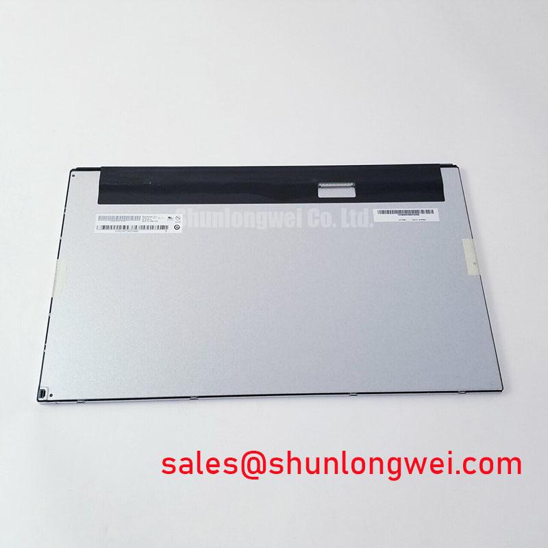
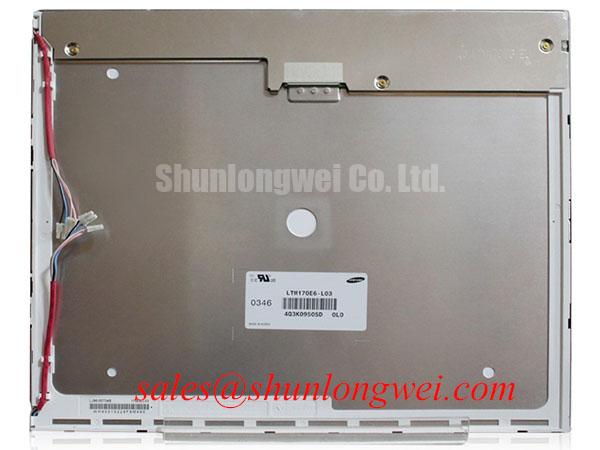
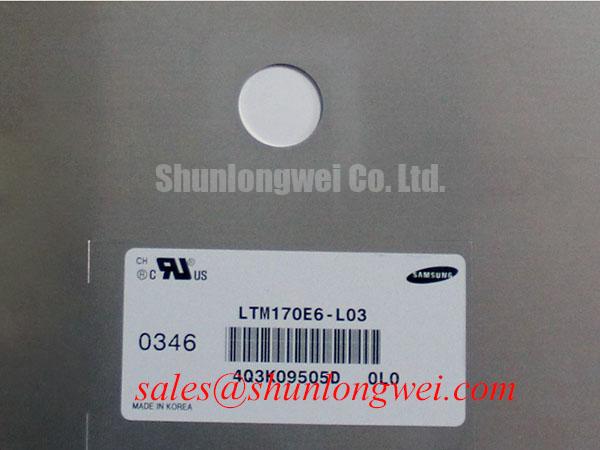
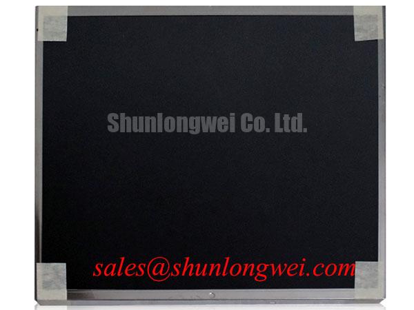
Begin the bench check with the original equipment documentation beside the display, then inspect the LTM170E6-L03 module for connector damage, bezel distortion, cracked glass, and visible pressure marks before applying power. The supplied factory record identifies this unit as a TFT-LCD Display Module in the Industrial Grade LCD/HMI Panel category, manufactured under the Samsung designation. Its specification status is listed as Official Factory Spec Verified. The available record does not confirm resolution, active-area dimensions, interface pinout, supply voltage, backlight technology, luminance, or operating-temperature limits, so these items must be matched against the original panel documentation before installation.
| Model | LTM170E6-L03 |
| Manufacturer | Samsung |
| Product category | Industrial Grade LCD/HMI Panel |
| Construction | TFT-LCD Display Module |
| Specification status | Official Factory Spec Verified |
For a failed industrial display, separate the image-generation path from the illumination path before removing the module from its chassis. With the unit connected to its known-good controller, perform a controlled primary-color bench check using red, green, blue, black, and white test fields where the system permits this. Observe whether the image content changes correctly, whether characters remain stable, and whether the panel presents a uniform dark field. This inspection is a practical diagnostic method rather than an LTM170E6-L03 factory acceptance limit.
A dark screen does not by itself prove a failed backlight. In a dim environment, place a flashlight at approximately 45 degrees to the viewing surface and look for a faint image shadow while the display is commanded to show an active signal. A visible but unilluminated image can direct the engineer toward the backlight supply, inverter or LED driver, enable signal, cable connection, or protection circuit. No visible image requires a wider check covering the host graphics output, panel timing electronics, interface continuity, and power sequencing. This method cannot confirm a microscopic driver or glass defect without comparison to a known-good signal path.
When examining vertical lines, horizontal bands, missing color areas, or intermittent sections, avoid assigning a single cause from the visual symptom. A defect may involve the display interface, connector contact, mechanical stress, timing electronics, or the panel’s bonded driver region. Confirm the observation by repeating the test with stable input content, recording the result at different brightness settings, and checking whether the pattern follows the display or remains with the host system.
For LVDS installations, the system integrator should verify the exact transmitter format, lane arrangement, differential polarity, pixel-clock relationship, and connector pin assignment from the original panel documentation. Do not assume that a mechanically matching connector proves electrical compatibility. Differential pairs should be routed as controlled-impedance signals with closely matched lengths, while the final impedance and skew budget remain system design requirements validated with the actual cable, connector, receiver, and enclosure.
💡 Pro Tip: Keep the differential clock and data routing consistent with the original harness geometry, and compare the clock eye and data timing at the panel connector rather than relying only on the source-side waveform.
Eye-Diagram Voltage Margin and Differential Noise Floor Verification in High-Vibration Bays
In equipment installed near switching power supplies, motor drives, pumps, or other high-noise assemblies, begin the signal investigation at the panel-side connector. Check the shield termination, cable seating, connector latch condition, and separation from high-current conductors. A cable that passes a static continuity check can still produce intermittent pixel jitter or horizontal noise when common-mode disturbance, vibration, or chassis movement changes the coupling path.
A 360-degree shield connection may be considered as part of the enclosure-level EMC strategy when it is compatible with the original system grounding architecture. This is a design consideration, not an LTM170E6-L03 certification claim. Ferrite suppression can also be evaluated where conducted noise is present, but the selected component, placement, and impedance profile must be determined from measured interference and the complete system topology. The display module itself should not be described as independently certified for a complete equipment-level EMC standard.
Use an oscilloscope with a suitable differential probe to compare the panel-side eye opening, common-mode behavior, clock stability, and data transitions against a known-good unit or an approved reference waveform. The purpose is to identify reduced voltage margin, excessive ringing, timing displacement, or coupling that appears only when nearby equipment operates. If the display fault changes when the cable is moved, the result may indicate a mechanical or interconnect sensitivity; repeat the test with the cable restrained and the enclosure assembled in its normal configuration.
Low-temperature operation requires a separate review of the panel documentation and the host system’s environmental specification. Liquid-crystal response can change with temperature, which may appear as longer gray-to-gray transitions, image smearing, or slow recovery after a frame change. These observations should not be converted into a guaranteed operating range for this model because the available factory record does not provide the required temperature limits or response-time data.
If the equipment uses a heater strip, the integrator should verify its control sequence, surface temperature distribution, electrical isolation, and effect on the panel frame. Heating should be evaluated as part of the complete enclosure design rather than connected directly to an assumed panel requirement. Confirm power-up behavior in the same order used by the original equipment, including controller readiness, display supply, backlight enable, and signal activation. Incorrect sequencing can create a no-image condition without proving permanent panel damage.
Chassis M3 Fastener Torque Sizing to Eliminate Optical Mura Defects
Mechanical integration should begin with a dimensional comparison between the removed display and the replacement candidate. Check the visible-area alignment, bezel opening, connector exit direction, mounting-hole position, rear clearance, cable bend path, and any locating features. The supplied record does not state the external envelope or mounting-hole dimensions for the LTM170E6-L03, so the original module or a verified mechanical drawing should be used as the reference.
Uneven frame pressure can produce localized brightness variation, dark corners, or visible mura even when the electrical signal is correct. This is why the chassis should be inspected for burrs, warped brackets, trapped cables, uneven gasket compression, and contact between the glass edge and the bezel. Fasteners should be tightened progressively in a cross-pattern so that the frame seats evenly. Any torque value must come from the original equipment manufacturer, the confirmed mechanical drawing, or a validated assembly process; the available product data does not establish a model-specific M3 torque limit.
Do not use a fastener to pull a misaligned panel into position. If the mounting holes do not naturally align, stop and resolve the dimensional issue before tightening. Designers should verify the tolerance stack between the panel, carrier plate, bezel, gasket, and display window under the assembled thermal condition. This approach reduces the risk of transferring enclosure stress into the viewing area while preserving the intended optical alignment.
Ambient light performance must also be verified from confirmed panel data rather than inferred from the model number. Contrast ratio, surface treatment, reflectance, and viewing-angle behavior can materially affect readability under direct sunlight or operating-room illumination. The available factory record does not publish a contrast-ratio value or confirm an anti-glare coating for this unit. Engineers evaluating the LTM170E6-L03 for surgical navigation or ultrasound diagnostic display equipment should therefore compare a powered sample under the actual front-window, lighting, and viewing-angle conditions.
The external window should remain free of point loading and should not press against the active display area. A rigid bezel can be useful for alignment, but its clear aperture, edge clearance, sealing method, and service removal path must be checked against the original equipment. These mechanical details are especially important where the panel is installed in a movable cart, articulated arm, or vibration-exposed diagnostic console.
Backlight Driving, Dimming, and Flicker Suppression
The backlight architecture of the LTM170E6-L03 must be confirmed from the original panel documentation before the replacement harness or driver is selected. The supplied factory record does not identify whether this specific module uses CCFL or WLED illumination, nor does it state ignition voltage, lamp current, LED current, PWM range, dimming ratio, luminance, or service-life data. A system integrator should not connect a modern constant-current LED driver to an unverified panel or assume that a legacy inverter can operate a different backlight architecture.
For a suspected illumination fault, check the backlight enable signal, supply path, driver protection status, connector condition, and brightness command while separately confirming whether image data is present. If a flashlight test reveals a valid image, measure the backlight circuit using instruments and procedures suitable for the confirmed technology. High-voltage backlight circuits require appropriate isolation and probing practice; the correct test limits must come from the applicable service documentation.
Where the host system provides PWM dimming, verify the input logic level, frequency range, polarity, minimum pulse behavior, and relationship between brightness command and visible flicker from the original documentation. A specified dimming ratio cannot be attributed to this model without a supporting factory source. If flicker is reported, inspect both the electrical waveform and the optical result with the real camera systems used around the equipment, because some imaging devices reveal modulation that is not obvious to the human eye.
LVDS or TTL timing should be checked at the panel connector after the cable, shielding, connector, and grounding scheme are installed. Confirm clock duty behavior, data hold relationship, reset behavior, and power-on sequencing against the host design. The correct voltage margin and jitter tolerance are interface-specific system values, not assumptions that can be taken from the product name. Where the display is considered for a high-precision surgical navigation or ultrasound diagnostic terminal, validation should include the complete controller, cable, display window, backlight driver, and enclosure.
For broader background on TFT-LCD operating principles, selection factors, and common integration misconceptions, consult The Ultimate Guide to Industrial TFT LCD Technology. Additional industry reference material may be reviewed through the Sharp Display Solutions Official Portal and Sharp Devices Europe Industrial Display Solutions. These resources provide general display engineering context and do not replace the LTM170E6-L03 documentation.
⚠️ Field Alert: Disconnect all panel and backlight cables before servicing, and verify the original pinout and power sequence before the first replacement-unit power test.
For procurement and repair review, identify the complete original panel label, connector configuration, host equipment model, and required environmental conditions before placing the unit into a surgical navigation or ultrasound display assembly. The LTM170E6-L03 should be treated as compatible only after those physical, electrical, optical, and timing conditions have been verified against the original system.