


Content last revised on September 24, 2026
Eye-Diagram Voltage Margin and Differential Noise Floor Verification in High-Vibration Bays
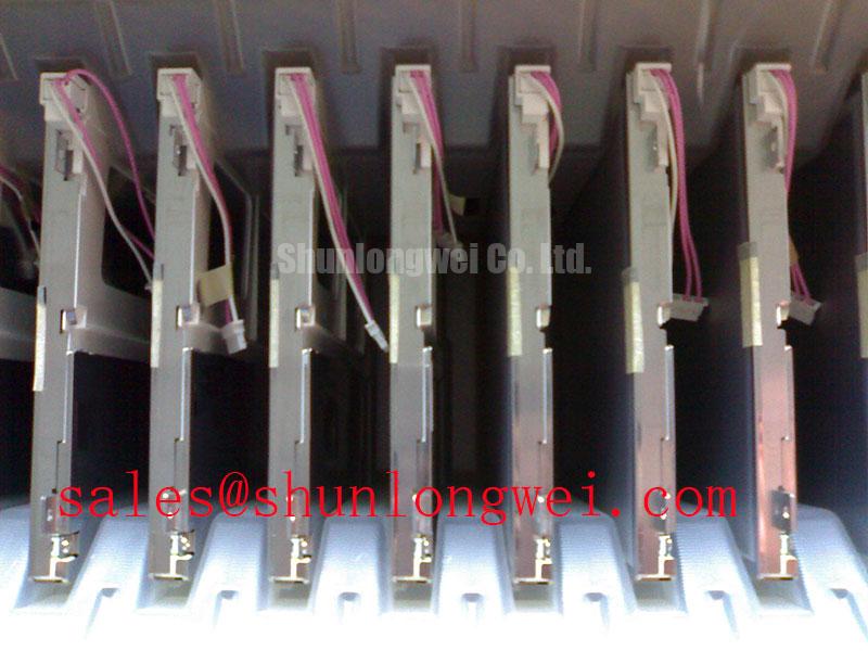
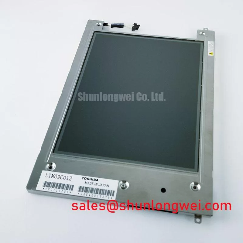
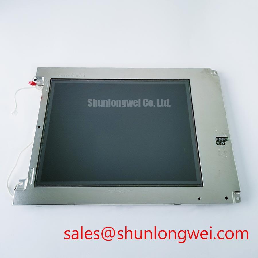
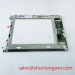
Begin service evaluation by checking the LQ9D011 label against the equipment documentation, inspecting the TFT-LCD module for cracked glass, lifted frame sections, damaged flex connections, and uneven bezel contact before applying power. The available factory information identifies this part as a Sharp Industrial Grade LCD/HMI Panel supplied as a TFT-LCD Display Module. The specification status is listed as Official Factory Spec Verified. Voltage, connector assignment, display resolution, viewing area, backlight configuration, and timing values should be confirmed from the original panel documentation before installation.
For maintenance engineers, the most important distinction is between a confirmed product identity and system-level integration data. The published information confirms the manufacturer, product category, and module construction, but it does not establish an interchangeable supply voltage, LVDS or TTL pinout, pixel clock, connector count, backlight current, or mechanical envelope. Those values must be matched against the display assembly being replaced rather than inferred from the model name.
When the LQ9D011 is evaluated near variable-frequency motor drives, servo amplifiers, or other switching equipment, begin with the signal path rather than adjusting display settings. Inspect the cable shield termination at both the display and controller ends, verify that the shield has a low-impedance chassis reference appropriate to the equipment design, and check whether the cable is routed alongside high-current motor conductors. A 360-degree shield termination can be considered where the enclosure and connector system support it, but the final grounding arrangement remains a system EMC decision.
Pixel jitter, intermittent horizontal bands, or unstable grayscale transitions can arise from several conditions, including differential-pair imbalance, common-mode interference, connector contamination, inadequate return-current control, or a controller timing problem. These symptoms should not be assigned to the LQ9D011 alone. Compare the suspect signal path with a known-good assembly and use an oscilloscope with suitable probing methods to examine the differential waveform, common-mode movement, eye opening, and clock relationship at the panel connector.
A ferrite component may be evaluated on an LVDS cable as a Design Consideration when common-mode noise is present, but its impedance profile must match the frequency range of the interference. Adding ferrite material without checking the signal waveform can increase edge distortion or create an unwanted resonance. Designers should verify the result during motor acceleration, deceleration, and worst-case cabinet loading rather than relying on a static bench test.
The LQ9D011 factory information supplied for this product does not state a backlight lifetime or an MTBF value. A frequently quoted brightness-life figure must therefore not be treated as an official rating for this module. For service planning, record luminance uniformity, backlight current, panel temperature, and startup behavior at defined inspection intervals. Any lifetime model should be based on the actual LED driver, thermal path, operating profile, and supporting test evidence.
Flashlight Dark-Shadow Optical Diagnostic to Isolate Logic and Backlight Fault Modes
With the display powered by a verified controller, first check whether the screen produces a stable full-field image. Use primary-color patterns to examine red, green, and blue response, followed by white, black, and mid-gray fields. This three-stage bench sequence helps separate image-data problems from illumination and optical-uniformity concerns without assuming a single failure mechanism.
If the screen appears dark but faint image content can be seen under controlled flashlight inspection, the observation may indicate that the panel logic is receiving image information while the illumination path is inactive. This is a diagnostic indication only. Confirm the result by checking the backlight enable path, driver output, connector seating, and current regulation circuitry against the original equipment schematic. If no image content is visible, inspect the logic supply, timing controller activity, cable continuity, and controller output before concluding that the display glass is defective.
Localized lines, repeating vertical features, or color-dependent defects require careful comparison across the primary-color patterns. A line defect may involve the panel interconnect, controller timing, cable integrity, or mechanical stress. It should not automatically be attributed to a microscopic driver connection failure. Avoid pressing the glass or frame while powered, since mechanical pressure can change the appearance of an existing defect and make the diagnosis less reliable.
Temperature testing should be performed only within the limits specified by the original equipment and panel documentation. During a controlled temperature transition, observe whether the image changes with supply stability, clock quality, or mechanical expansion. TTL and LVDS transmitter behavior, including clock jitter and data hold time, is determined by the controller and interface implementation; those values must be verified from the associated electronics rather than assigned to the LQ9D011 without documentation.
20-Pin and 30-Pin Differential LVDS Timing, Pixel Clock, and Skew Compensation
Do not select a cable or controller based only on an apparent connector fit. The supplied factory data does not confirm whether a particular LQ9D011 installation uses a 20-pin or 30-pin interface, nor does it confirm the electrical mapping. The system integrator should verify the required supply voltage from the original panel documentation and cross-check every connector position, ground return, enable signal, clock pair, data pair, and backlight connection before energizing the assembly.
Where the interface is LVDS, route each differential pair as a controlled transmission path with a continuous reference plane and consistent pair geometry. A nominal 100 Ω differential characteristic impedance is a Design Consideration commonly used for LVDS routing, but the controller, cable, connector, and PCB stackup must be considered together. Designers should verify the completed channel with signal-integrity measurements rather than treating the nominal value as proof of compatibility.
JEIDA and VESA data mapping are not interchangeable assumptions. Incorrect mapping can produce abnormal colors, split-screen effects, reversed grayscale behavior, or an image that appears synchronized but is visually invalid. Confirm the mapping from the original controller documentation and compare the data order with a known-good panel. Pixel clock frequency, frame timing, and data hold margins also belong to the complete display system; the available LQ9D011 product information does not provide those values as standalone module specifications.
Power sequencing should be checked against the panel documentation and controller design. Confirm that the logic rail reaches its permitted operating range before enabling data transmission or the backlight, and observe the actual rise and enable relationship with an oscilloscope. The timing values supplied as a general integration target should be treated as an Engineering Recommendation only, not as an official LQ9D011 requirement. If the replacement display is being evaluated alongside another Sharp display solution, the LM64P10 can be reviewed as a separate reference point for related display-system planning; it should not be assumed electrically interchangeable.
For cross-model assessment, the LM190E08-TLG6 may be examined as another display option during an engineering comparison. Any substitution requires confirmation of active area, resolution, interface mapping, mounting envelope, backlight control, connector orientation, and controller compatibility. Similar appearance or manufacturer branding is not sufficient evidence of a drop-in replacement.
Flush-Mount Open-Frame Bezel Integration and Perimeter Gasket Shock Isolation
Before fitting the LQ9D011 into an industrial HMI or a potential surgical navigation or ultrasound display assembly, measure the host opening, panel support surfaces, connector clearance, cable bend path, and rear-component space. The supplied product data confirms the TFT-LCD module category but does not provide a verified outer bezel drawing or mounting-hole pattern. The cabinet designer should therefore use the original mechanical drawing or inspect the installed assembly directly before machining a replacement opening.
A perimeter gasket should provide continuous environmental separation without transferring concentrated force into the glass, frame, or flex area. Check for gaps at corners, compression marks, displaced adhesive, and contact with sharp chassis edges. The gasket material, compression behavior, and sealing level remain enclosure design matters. They should be validated against dust, humidity, vibration, and cleaning-fluid requirements for the finished equipment.
Use a cross-pattern tightening sequence when the host assembly uses multiple fasteners, allowing the frame to settle evenly. The commonly referenced M3 fastening range of 0.35 to 0.45 N·m is a general Design Consideration for a suitable metal mounting arrangement, not an official LQ9D011 factory limit. The actual value must follow the chassis material, fastener specification, gasket construction, and original service documentation. Uneven loading can create optical nonuniformity, frame distortion, or intermittent connector stress even when the display initially operates.
⚠️ Maintenance Note: Inspect the cabinet airflow path and perimeter gasket condition during scheduled service, and disconnect power before removing or inserting any display cable.
Thermal management should avoid placing a concentrated heat source behind one region of the panel. Check airflow around the backlight driver and controller area, then compare the display surface for localized brightness or color changes after stabilization. Do not assign a specific brightness decay curve or operating-life value to the LQ9D011 without an applicable Sharp document or qualified test report. The engineering reference Industrial Display & HMI Solutions can support broader enclosure and integration planning, while final acceptance should remain based on measured interface behavior, mechanical fit, image quality, and the original equipment requirements.