

Content last revised on October 9, 2026
Full-Screen Inspection: Pixel Defects and Background Uniformity
Begin the powered inspection with the original, compatible display controller wherever practical. As a Design Consideration, a useful inspection sequence is a uniform illuminated field, a uniform dark field, and a repeating pattern that exercises the addressable display area. Use patterns supported by the actual display architecture. Primary-color testing is appropriate only where the documented module and controller support color operation; it should not be assumed from a generic LCD description.
Observe whether an irregularity remains fixed in the same physical position as the image changes. A stationary mark, a missing line, and a moving disturbance warrant different checks, but none establishes a single cause by appearance alone. Compare the displayed pattern with the controller output and, where available, an equivalent functioning assembly. Keep brightness and viewing position consistent so that changes in observation conditions do not resemble changes in panel performance.
For background nonuniformity, inspect the complete optical path before attributing the symptom to the display itself. Contamination on the protective window, uneven bezel pressure, reflections, and illumination variation can overlap visually. Oblique illumination can help distinguish a surface mark from an image-area irregularity, but it cannot establish an internal driver fracture. Do not press the viewing surface or flex the module to provoke a fault.
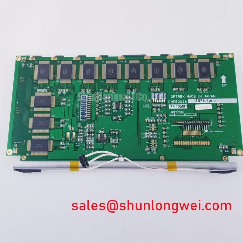
If lines or incomplete image areas persist, inspect accessible connectors, cable contacts, and host-board connections with power removed. Then examine the documented interface at the receiving end using suitable measurement equipment. The system integrator should verify the actual interface type from the original panel documentation before choosing a probe arrangement or interpreting a waveform.
Timing assessment should follow the manufacturer’s stated clock, setup, hold, and signal-level requirements. No TTL or LVDS timing margin is established here for this model. As an Engineering Recommendation, compare measured behavior with the documented limits under the equipment’s permitted operating conditions, including relevant temperature changes. A nominally correct clock frequency alone does not demonstrate adequate receiving margin.
Keep the acceptance record practical: photograph the test pattern, note the controller configuration, and record whether the symptom changes after a connector is correctly reseated. For purchasing decisions, request the matching outline drawing and connector information alongside the complete model designation. A clear image on a bench does not by itself confirm mechanical or electrical compatibility with the installed equipment.
Investigating Pixel Jitter and Horizontal Lines Near Motor Drives
When image disturbance coincides with motor operation, compare the display during drive-disabled, enabled, and moving conditions using the machine’s approved service procedure. This is a Design Consideration for troubleshooting, not a claim that the DMF-50174NFL-SFW-11 has a particular immunity rating. Record whether the disturbance follows switching activity, load changes, cabinet movement, or an unrelated event before changing hardware.
Start with the existing installation. Check whether the display cable has been rerouted beside motor conductors, whether an intended chassis bond is loose, and whether a cable shield has lost its original termination. Restore the documented arrangement before experimenting with additional suppression. The correct shielding method depends on the cable construction, interface, enclosure, and equipment grounding scheme; a universal instruction to ground every cable in the same way is inappropriate.
As a Design Consideration, reduce unnecessary coupling between power wiring and sensitive display connections while preserving the approved cable arrangement. Where a shielded connection is specified, inspect the continuity and physical quality of its intended termination. Do not assume that an exposed flexible cable provides the same shielding behavior as a screened cable assembly, or that adding conductive tape creates an acceptable replacement.
Ferrite suppression should be evaluated at equipment level rather than treated as a guaranteed repair. Its effect depends on the disturbance spectrum and the current path through the assembly. An engineering assessment should compare the image and relevant electrical measurements before and after a proposed change, while confirming that the modification does not compromise connector retention, cable bending, or enclosure closure.
Check display supply behavior separately from image-data integrity. A disturbance that appears during drive operation can involve power distribution, signal coupling, grounding, or more than one mechanism. Measure at appropriate points using safe probing practices and compare against the original electrical limits. Avoid diagnosing every horizontal line as electromagnetic interference simply because a motor drive is nearby.
The Ultimate Guide to Industrial TFT LCD Technology provides broader background for separating display, interface, and integration questions; technology-specific details still require confirmation for this exact module. Equipment EMC performance remains a property of the assembled system and its installation, not an independent compliance guarantee supplied by the display.
Thermal Cycling, Gasket Fit, and Condensation Control
Inspect the bezel and mounting surfaces before refitting the display. As a Design Consideration, trapped debris, a displaced gasket, or uneven support can introduce local loading and compromise the enclosure seal. Check that the mounting arrangement supports the module as intended without using screw force to pull a misaligned assembly into position. Tightening torque and sequence should come from the equipment or module documentation.
Evaluate visible nonuniformity with the display correctly supported. If appearance changes after the enclosure is assembled, compare gasket seating, bracket alignment, and cable routing before concluding that the LCD has deteriorated. Mechanical pressure can affect optical appearance, but an observed bright or dark region is not sufficient evidence of a particular internal defect. Repeatedly loosening and overtightening the assembly is not a controlled diagnostic method.
Temperature assessment must remain within the documented operating and storage limits. No numerical temperature range is established here for the DMF-50174NFL-SFW-11. As a Design Consideration, liquid-crystal response can change with temperature, so an image that responds differently after a cold start should be assessed against the manufacturer’s conditions rather than an assumed industrial temperature class.
Condensation requires separate attention from temperature rating. During movement between environments, moisture can accumulate on surfaces even when the eventual operating temperature is acceptable. The equipment maintenance procedure should determine when inspection and stabilization are sufficient before energization. Do not accelerate drying with unqualified local heating or apply cleaning agents without checking compatibility with the exposed surfaces and enclosure materials.
Maintenance Note: During scheduled servicing, inspect ventilation paths and perimeter gaskets for blockage, displacement, or deterioration before returning the display assembly to operation.
Do not assign adhesive chemistry, sealant composition, or thermal-cycle endurance to this model without manufacturer documentation. Service records should instead capture observable conditions: gasket damage, mounting distortion, moisture traces, connector condition, and repeatable image changes. These observations support maintenance decisions without inventing a remaining service life or treating an environmental symptom as proof of irreversible panel damage.
Viewing-Angle, Ambient-Light, and Touch-Overlay Compatibility
Assess readability from the actual operator positions before approving an installation. Neither a symmetric viewing cone nor an IPS, MVA, or TN designation should be assigned to the DMF-50174NFL-SFW-11 without its model-specific optical specification. As a Design Consideration, examine the displayed information from the intended standing, seated, and off-axis positions with the final bezel and protective window installed.
Use representative interface content rather than a bright test screen alone. Fine text, alarm indicators, shaded controls, and neighboring tones can expose readability limitations that a uniform field conceals. Keep the controller settings consistent during comparison. If the equipment allows image adjustments, distinguish an acceptable configuration change from a workaround that hides missing information or reduces the visibility of critical status indications.
Ambient-light performance belongs to the complete optical assembly. Reflections from the protective window, panel orientation, contamination, and surrounding illumination can dominate what the operator sees. Anti-glare and anti-reflection treatments are different approaches, and neither is confirmed here as a factory feature of this module. Any added optical layer should be assessed for reflections, image clarity, cleaning compatibility, and mechanical clearance.
A touch overlay is also a separate compatibility question unless explicitly included in the documented assembly. The LCD model designation alone does not establish glove operation, wet-touch behavior, touch technology, or controller compatibility. When retaining an existing overlay, verify its mounting, cable clearance, controller connection, and calibration procedure. Assess glove and moisture behavior through the equipment’s approved functional checks rather than assuming capability from the display category.
The DMF-50174NFL-SFW-11 can be evaluated for an existing CNC operator panel or robot teach pendant only after the original equipment requirements have been compared with the complete module documentation. Confirm the visible area, mounting references, connector location, cable movement, optical orientation, and interface requirements. For handheld equipment, include the effect of enclosure closure and normal cable movement in that assessment without assigning an undocumented vibration rating.
Before returning the assembly to service, verify readability and control operation in its installed position under representative lighting. Record any viewing-position limitations, check that the protective window is clean, and confirm that the bezel does not obscure necessary information. Backlight lifetime, brightness retention, and contrast figures should be taken from the exact manufacturer specification; no generic lifetime claim should substitute for those data in a replacement decision.