

Content last revised on September 22, 2026
Incoming Inspection of the NEC NL12876BC15-01 LCD Module
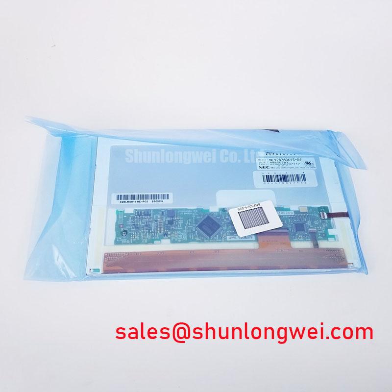
Begin the incoming inspection by checking the NEC NL12876BC15-01 against the equipment documentation, then examine the display surface, frame, connector area, and label before applying power. This industrial-grade LCD/HMI panel is identified as a TFT-LCD Display Module. The available product data confirms the manufacturer and product category, but it does not establish an unverified interface voltage, resolution, backlight lifetime, viewing angle, or environmental rating.
For an AGV or forklift telematics display replacement, mechanical fit and electrical compatibility must be treated as separate checks. Compare the original panel’s mounting geometry, active display area, cable exit position, connector keying, controller board, and display timing documentation. A matching model number does not by itself confirm that a different controller, cable assembly, or power arrangement will operate correctly.
| Item | Verified information |
|---|---|
| Model | NL12876BC15-01 |
| Manufacturer | NEC |
| Product category | Industrial Grade LCD/HMI Panel |
| Construction designation | TFT-LCD Display Module |
| Specification status | Official Factory Spec Verified |
The system integrator should verify the required supply voltage from the original panel documentation. Do not infer a 3.3 V or 5.0 V requirement from the model number, and do not assume that a replacement harness follows the same pin assignment as another NEC display. The same caution applies to LVDS, TTL, JEIDA, and VESA terminology: the panel interface and mapping should be confirmed from the corresponding technical documentation before connection.
Controlled Differential Flex Routing and Timing Verification
When this display is evaluated for a rugged AGV or forklift dashboard, inspect the complete signal path rather than the panel alone. A display image that is split, unstable, intermittently blank, or populated with moving noise can involve cable seating, connector contact, controller timing, supply sequencing, or differential-pair routing. Use a known-good signal path where available and compare the incoming clock and data behavior with an oscilloscope or suitable high-speed measurement method.
Design Consideration: If the host system uses a differential display link, the routing should preserve the interface’s specified characteristic impedance and pair relationship. A commonly used design target is 100-ohm differential impedance, but that value must be confirmed against the original controller and panel interface specification rather than treated as an NEC factory parameter for this model. Keep the pair lengths and return path consistent, minimize unnecessary stubs, and avoid routing the display cable beside high-current motor, brake, inverter, or servo wiring.
In a vehicle display enclosure, flex-cable movement can change contact pressure and introduce intermittent faults. Secure the cable so that vibration is not transferred directly into the panel connector. The connector should be inserted squarely, with its contacts aligned and its locking feature fully engaged. A cable that appears connected but sits at an angle can produce symptoms that resemble timing or controller failure.
Power-on behavior also requires documentation-based verification. The host designer should confirm the panel supply rail, enable signals, reset behavior, backlight control, and data-valid timing from the original panel documentation. If the system specifies a controlled rise time, measure it at the display connector under the real harness and load conditions. A bench power supply reading alone does not confirm that the panel receives clean power during vehicle startup, contactor operation, or motor acceleration.
JEIDA and VESA data mapping should be checked at the controller output and against the documented panel input. Incorrect color-bit mapping can create unusual grayscale behavior, incorrect primary colors, or a stable image with visibly wrong tones. These symptoms should not be assigned to the LCD glass without first checking the mapping, clock polarity, timing controller configuration, and gamma-related settings on the host board.
For sub-zero evaluation, response time can change as liquid-crystal behavior changes with temperature. Any stated operating range, gray-to-gray response value, heater-strip requirement, or startup timing must come from the applicable factory documentation. If a heater is part of the equipment design, its control strategy should be validated at the panel surface and connector area while monitoring image recovery, current draw, and condensation risk. The system engineer must determine the acceptable stabilization time for the actual AGV or forklift operating cycle.
Thermal Cycling and Perimeter Sealing Checks
Thermal cycling should be assessed as an assembly-level reliability exercise, not as proof of a specific factory lifetime for the NL12876BC15-01. The available verified data identifies the unit as a TFT-LCD display module but does not provide a confirmed thermal operating range, sealant construction, liquid-crystal viscosity profile, or adhesive qualification record. Those items should be obtained from the applicable panel documentation before they are used in a purchasing or design decision.
Design Consideration: A cold display may show slower image transitions, visible trailing, or temporary grayscale nonuniformity while the panel reaches a stable condition. These observations require controlled comparison at known temperatures and with consistent image patterns. Record the supply condition, input timing, ambient condition, warm-up period, and measured image behavior. Avoid treating one cold-start observation as a permanent defect without repeating the test after the assembly has stabilized.
For an enclosure mounted on an AGV or forklift, inspect the bezel interface and any compression points after thermal exposure. Mechanical stress can be introduced when the display frame and enclosure expand at different rates. Check for changes in surface pressure, cable strain, connector movement, and visible edge lifting. The inspection should be performed with the panel unpowered and powered so that both physical changes and image changes are documented.
A perimeter gasket or sealant may be used in the larger equipment enclosure, but its material, thickness, and qualification are not confirmed for this model. Do not describe the display as sealed, waterproof, or suitable for a specific ingress-protection rating unless the complete display assembly and enclosure carry the required documentation. The panel itself should not be used as evidence that the finished telematics terminal meets an environmental certification.
Condensation is another system-level concern during rapid temperature transitions. Designers should consider airflow, enclosure pressure equalization, surface temperature, and cable-entry sealing, then verify the result through the equipment’s own environmental test plan. If image recovery is delayed after a cold start, compare the display with the controller output and check whether the delay follows the panel, the power rail, or the host timing configuration.
For procurement teams, the useful record is a traceable inspection sheet containing model identification, physical condition, connector condition, visual test results, and the documentation used for electrical approval. This separates verified product information from assumptions made during integration.
Polarizer and Optical Inspection Under Industrial Lighting
Optical inspection should begin with a uniform white field, followed by red, green, blue, black, and mid-gray patterns. Observe the display directly and from the intended operator position while recording visible nonuniformity, pixel anomalies, edge leakage, flicker, color imbalance, and changes caused by cable movement. The NEC NL12876BC15-01 product information supplied here does not confirm a contrast ratio, viewing-angle specification, anti-glare treatment, polarizer type, or optical retardation-film construction.
Direct industrial lighting can make a functioning display appear weak even when the signal path is correct. Evaluate the panel under the actual equipment lighting direction and compare the result with a controlled lower-light condition. A hood, bezel, or change in viewing angle may alter perceived contrast, but these are enclosure decisions rather than confirmed characteristics of the panel.
Design Consideration: TN, IPS, and MVA terminology should not be assigned to this model without supporting documentation. Viewing-angle figures such as 85 degrees in four directions, or a contrast figure above 500:1 under a defined illumination level, must be treated as specification values only when stated by the applicable factory source. They should not be inferred from a visual bench inspection.
Use a stable test image for gamma and grayscale evaluation. If the mid-gray steps appear compressed or shifted, verify the host timing controller, gamma reference configuration, video source, and measurement setup before attributing the condition to the panel. A panel can display incorrect grayscale because the controller is using an unsuitable lookup table or because the signal mapping does not match the input format.
Inspect the surface for scratches, pressure marks, contamination, and localized brightness changes under angled illumination. A dark-room inspection and a normal production-floor inspection can reveal different defects. Keep the viewing distance and light position consistent so that results can be compared between a replacement unit and the removed display.
For AGV and forklift applications, optical approval should also include operator readability during vibration and changing ambient light. The display’s readability depends on the panel, cover window, bezel geometry, lighting, viewing direction, and software color scheme. The equipment designer should validate the complete assembly rather than relying on the LCD module description alone.
For a broader explanation of panel selection, timing behavior, and industrial TFT-LCD terminology, engineers can consult The Ultimate Guide to Industrial TFT LCD Technology.
Mechanical Stress Screening and Primary-Color Fault Isolation
Mechanical inspection should be performed before repeated insertion, removal, or powered testing. Check the glass perimeter, frame, connector housing, flex attachment area, and mounting points for visible damage or distortion. Do not press on the active area while attempting to reproduce an intermittent image; pressure can alter the symptom and add mechanical risk without identifying the original cause.
A practical three-stage bench screen uses a full-screen red field, a full-screen green field, and a full-screen blue field, followed by black and white checks. The purpose is to identify localized pixel irregularities, color-channel problems, uneven illumination, and regions that respond differently from the rest of the screen. Record the exact pattern, location, and repeatability instead of assigning a single cause from one observation.
A 45-degree flashlight inspection can help separate surface contamination, optical nonuniformity, and shadow-like areas from active image defects. Perform the check with the display off and then compare it with a powered black field. If a line or region remains visible only under angled illumination, inspect the surface and optical stack externally. If it appears in the powered image, compare the input signal, timing, connector seating, and controller output before drawing a panel-level conclusion.
💡 Bench Tip: Disconnect power before inserting or removing the display cable, use ESD protection, and keep the flex cable flat and square while engaging the connector lock.
Do not claim a specific LED backlight lifetime or an MTBF decay curve for this model without the relevant factory test data. The available verified information does not establish a 50,000-hour rating, a 50 percent brightness endpoint, or a constant-current backlight architecture. If the display assembly includes a separate backlight driver, test its current regulation, enable behavior, thermal condition, and output stability according to the driver documentation.
When comparing replacement options, engineers should match the complete electrical and mechanical interface rather than selecting by appearance or nominal screen class. A potentially relevant product for a separate same-size or same-resolution evaluation is NL8048AC19-13KD; its compatibility must be verified independently against the original equipment documentation.