

Content last revised on September 26, 2026
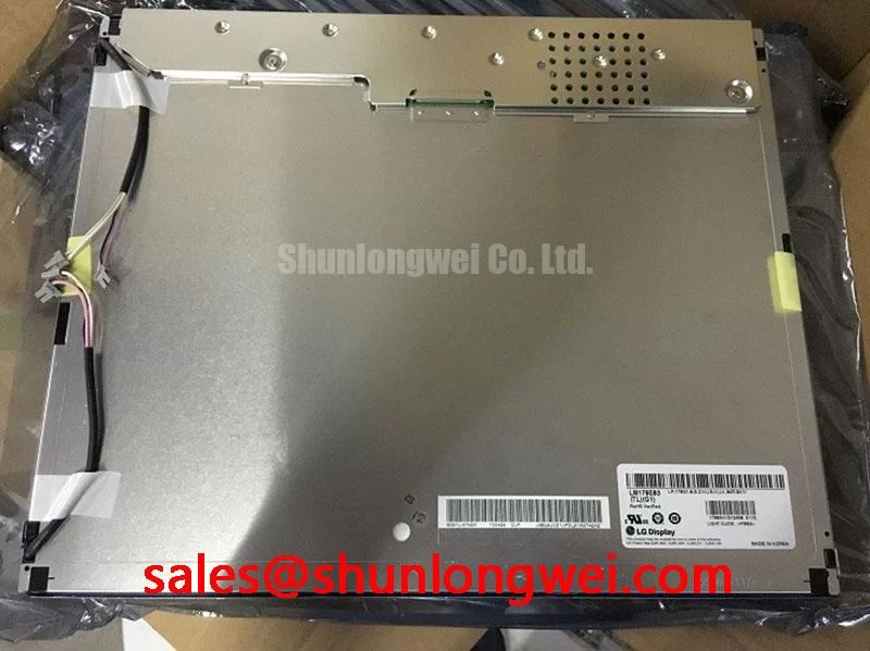
LM170E03-TLG1 LG Display TFT LCD Display Module
Check the original panel label, connector condition, and host equipment documentation before applying power to LM170E03-TLG1; the available product information identifies it as a TFT LCD Display Module manufactured by LG Display. Suitability for industrial HMI use must be verified against the panel specifications and equipment requirements.
| Item | Product information |
|---|---|
| Model | LM170E03-TLG1 |
| Manufacturer | LG Display |
| Product category | TFT LCD Display Module |
| Product form | TFT LCD Display Module |
| Specification status | Verify ratings and interface details against the original panel documentation |
This product page intentionally separates product identity from system level integration assumptions. The information available here does not confirm the display resolution, active area, luminance, viewing angle, interface voltage, connector pinout, backlight type, or mechanical outline. The system integrator should verify those values from the original panel documentation and the equipment service file before approving a replacement.
Optical Luminance Degradation Curve and CCFL to LED Modernization Retrofit Pathways
When servicing an AGV or forklift telematics display, begin with a controlled visual inspection. Compare the replacement panel with the removed unit under the same ambient light and check the visible image area, bezel relationship, connector location, and backlight behavior. A dark screen can result from the panel, the host video path, the backlight supply, or the control signal, so a complete diagnostic should not treat the symptom as proof of a single failed subassembly.
The model identity identifies a TFT LCD display module, but the information available here does not confirm whether this particular variant uses a cold cathode fluorescent lamp or an LED backlight. Do not substitute a constant current LED driver for an existing high voltage lamp circuit without confirming the original backlight architecture. A retrofit changes the electrical load, startup behavior, dimming method, thermal distribution, and enclosure wiring. The complete assembly must be reviewed rather than treating the optical panel as a drop in equivalent.
For a panel using a fluorescent backlight, the service engineer should verify the inverter output, ignition behavior, lamp wiring insulation, and shutdown response according to the original equipment documentation. For a panel using LED illumination, the engineer should verify the backlight enable signal, current regulation method, open circuit response, short circuit response, and dimming interface. The LM170E03-TLG1 information available here does not establish a specific backlight voltage, current, PWM frequency, or half brightness life value.
Long term luminance evaluation should be based on measured brightness at defined operating conditions rather than an assumed service life. Ambient temperature, driver current, enclosure ventilation, optical contamination, and duty cycle can all influence the observed degradation curve. The The Ultimate Guide to Industrial TFT LCD Technology provides broader background for selecting test methods and interpreting industrial TFT display behavior.
For a potential AGV or forklift installation, compare the original display at cold startup, normal operating temperature, and maximum expected enclosure temperature. Observe whether the image reaches stable luminance without intermittent dimming, audible electrical noise, or delayed backlight activation. These are integration checks, not confirmed performance specifications for LM170E03-TLG1.
Aluminum Heat Spreader Sizing and Thermal Interface Placement along Narrow Display Edges
Thermal work should start with the installed assembly rather than the LCD module alone. Record the position of the display, controller board, backlight driver, heater vents, and enclosure openings. Narrow display edges may sit close to metal brackets or polymer bezels, and mechanical contact can transfer heat unevenly or introduce stress into the panel frame. The external structure should therefore be reviewed for both temperature distribution and mounting pressure.
An aluminum spreader rail can be considered when a measured hot spot is concentrated near a driver board or backlight region. This is a Design Consideration, not an LM170E03-TLG1 factory requirement. The rail should have a defined mechanical support function, avoid loading the active display area, and use an interface method compatible with the enclosure materials. The system engineer must verify the resulting temperature profile during operation, startup, and shutdown.
Do not infer LED lifetime from an industrial display category. The available product data does not provide a confirmed LED lifetime, L70 value, B50 value, MTBF figure, or luminance maintenance curve for this model. If the original equipment documentation specifies such data, test the complete panel and driver combination under the stated conditions. If it does not, record measured luminance at agreed inspection intervals and identify the test temperature, drive condition, and duty cycle in the service record.
Mechanical installation also deserves a direct check. Compare the original screw locations, support points, bezel compression, cable bend path, and connector clearance. A replacement that fits the opening but transfers force through the glass or polarizer may show image nonuniformity or intermittent operation after vibration exposure. Designers should use the original mounting scheme where possible and verify the result with the actual enclosure, especially when the display is evaluated for a moving AGV or forklift terminal.
Pro Tip: Keep video and backlight wiring physically organized during bench testing so that a display fault can be separated from coupling, grounding, or enclosure related interference.
Polarizer Durability and Optical Retardation Film Inspection under Direct Industrial Lighting
Inspect the optical surface before installation under both diffuse and directional light. Look for scratches, pressure marks, contamination, edge lifting, uneven reflection, and image areas that change appearance when viewed from different positions. These checks help distinguish surface or mechanical issues from video timing problems. The information available here does not confirm an anti glare coating, anti reflection treatment, polarizer material, retardation film structure, or viewing angle specification for LM170E03-TLG1.
Direct sunlight and high bay lighting can reduce practical readability even when the electronic image is operating correctly. A system integrator should evaluate the complete display behind the intended cover, bezel, and protective window. Reflections can be introduced by the enclosure window or by an air gap, while a tinted cover can alter color and luminance. Any optical treatment must be validated with the actual viewing position used by the operator.
Do not assume a TN, IPS, or MVA optical configuration from the product category alone. The available information identifies the unit as a TFT LCD Display Module but does not confirm its panel mode, grayscale inversion characteristics, symmetric viewing cone, contrast ratio, or response time. If the equipment requires a particular viewing direction, compare the original panel and proposed unit using the same test image, camera position, ambient illumination, and display settings.
For AGV and forklift telematics equipment, vibration and repeated operator contact can affect the external optical stack without producing an immediate electrical failure. Check the bezel for localized pressure, inspect cable retention, and verify that the protective window does not touch the active display surface. A visible color shift or uneven gray field should be compared with a known good signal path before attributing it to the LCD cell itself.
Cold operation should also be verified at the equipment level. The information available here does not state a guaranteed operating temperature range, cold start response time, or compensation requirement for this model. Designers should confirm the original documentation and test image stability after the entire enclosure has reached the expected low temperature. This test should include the host controller, power supply, video cable, and backlight driver rather than the panel in isolation.
Logic Supply Voltage Sequencing and LVDS Data Mapping Verification
Before connecting LM170E03-TLG1 to a replacement controller, identify the original connector pinout and perform continuity and resistance checks on the host side with the equipment powered down. Confirm the logic supply, ground return, display enable signals, video connections, clock arrangement, and backlight control lines from the original documentation. The available product information does not confirm a 3.3 V or 5.0 V logic supply, an LVDS or TTL interface, JEIDA or VESA mapping, connector part number, or power sequencing limits.
The system integrator should verify the required supply voltage from the original panel documentation. Applying a guessed voltage can damage the panel electronics or create an ambiguous startup condition. A suitable bench procedure includes current limited power, a verified ground reference, observation of the enable sequence, and comparison of the video waveform with a known good assembly. Any rise time or delay requirement must come from the panel specification or the controller design documentation rather than from a generic LCD rule.
For an LVDS implementation, check pair assignment, polarity, lane order, clock relationship, termination arrangement, and data format. A JEIDA or VESA mismatch can produce incorrect colors or grayscale artifacts. Other mapping, timing, or signal integrity problems can produce split images, unstable synchronization, or patterned artifacts. These symptoms may also arise from a damaged cable, inadequate grounding, connector contact variation, or a controller configuration error, so the signal should be checked at the panel connector against a known good path.
Do not assume a particular differential impedance, pixel clock limit, hold time, or jitter margin for this model without the correct datasheet revision. As a Design Consideration, routing should minimize unnecessary discontinuities, maintain a controlled return path, and separate high current backlight switching nodes from sensitive video wiring. Final routing, timing margin, and EMC performance must be verified by the system designer in the completed enclosure. The display module itself should not be represented as independently certified for whole equipment EMC compliance.
PWM dimming also requires interface confirmation. The information available here does not specify a PWM input, supported frequency range, duty cycle linearity, or flicker performance. If the host uses PWM control, verify the required signal level and operating range from the original backlight documentation. If the module uses another brightness control method, preserve that method rather than adding an unverified PWM source. Oscilloscope measurements should be taken at the panel interface while the display is operating in the actual controller configuration.
During final compatibility testing, verify the image at startup, after a warm restart, after a complete power removal, and during changes in backlight level. Record the panel identity, controller revision, cable assembly, supply behavior, and observed display condition. This documentation gives repair engineers a repeatable basis for evaluating LM170E03-TLG1 in industrial HMI, AGV, and forklift telematics equipment without treating unconfirmed interface or optical values as factory specifications.